The configuration, required to launch the application in cluster mode is described using a standard Open Inventor scene graph with specific ScaleViz nodes. This scene graph can be made in two ways:
| - By describing it in a configuration file |
| - By describing it programmatically |
![[Important]](../../images/important.jpg) | |
The ScaleViz configuration file uses Open Inventor format, unlike the oiv.cfg file, which contains a list of name-value pairs (see SoPreferences SoPreferences SoPreferences ). |
A valid ScaleViz configuration file must have one of the following header strings:
#ScaleViz V8.0 ascii
or
#ScaleViz V8.0 binary
| |
The V6.0 and V7.0 ScaleViz configuration files are still loadable by ScaleViz 8.0, and are internally converted to ScaleViz 8.0 file format. Nevertheless, we highly recommend the use of the new file header. |
Starting with ScaleViz 7.0, a ScaleViz file supports the definition of a set of available cluster configurations. Each configuration must be defined by a scene graph always starting with a head node of type SoScaleVizConfig SoScaleVizConfig SoScaleVizConfig and can be named using the name field.
Here’s what a ScaleViz configuration file looks like:
#ScaleViz V8.0 ascii

    ScaleVizConfig
    {
    name "Config 1"

      ...
    }

  ScaleVizConfig
    {
    name "Config 2"

      ...
    }

  ...
|
Examples of ScaleViz configuration files can be found in: $OIVHOME/data/ScaleViz/config
In order to run in cluster mode, your application sends requests to the ScaleViz daemon. The application is aware of the ScaleViz daemon location by checking the SoMasterConfig SoMasterConfig SoMasterConfig node that must appear in the loaded configuration. The SoMasterConfig SoMasterConfig SoMasterConfig defines the daemon connection properties by its fields:
hostname specifies the network name or IP address of the node where the ScaleViz daemon is running (default is localhost).
port specifies the TCP port on which the daemon is listening for the connection (default is 3456).
A valid configuration is specified by a set of rendering nodes from the following:
- SoScreen SoScreen SoScreen : Used to visualize scene in an immersive environment.
- SoFlatScreen SoFlatScreen SoFlatScreen : Used to visualize scene on large tiled rendering wall.
- SoTileComposer SoTileComposer SoTileComposer : Used to define a tile compositing configuration.
- SoDepthComposer SoDepthComposer SoDepthComposer : Used to define a depth compositing configuration.
Other nodes like SoClusterGateway SoClusterGateway SoClusterGateway and SoScaleVizParameters SoScaleVizParameters SoScaleVizParameters may also be needed in your configurations to define specific settings of your visualization layout.
The use of these nodes is covered in subsequent sections.
The user can setup the configuration using a configuration file or programmatically. By default, at application startup, ScaleViz tries to load a configuration file defined in the environment (including an oiv.cfg file) by the SCALEVIZ_CONFIG_FILE variable. The variable defines the full path to the file to load. Programmatically, you can manage available configurations by building the configuration scene graph using ScaleViz nodes and adding/removing the built configuration to/from the set of all available.
Starting with ScaleViz 7.0, dynamic connection and disconnection is supported. Thus, a user can run
first in standalone mode and then decide to connect to a visualization cluster. He can then disconnect from the cluster and continue to work with the application locally.
The ScaleViz control dialog can be opened using the SHIFT + F9 key combination, and provides access to the complete set of ScaleViz parameters, including connection and disconnection. You can also manage connection and disconnection programmatically by calling SoScaleViz::connect() and SoScaleViz::disconnect().
Defining SCALEVIZ_AUTORUN in your environment will force your application to start with cluster rendering at startup. In this case, the first defined configuration is used when launching ScaleViz.
Applications may want to use cluster resources, even if the cluster is not physically close. Performance is thus impacted by network connection properties (bandwidth/latency). This is particularly true when using compositing configurations where frames or sub-frames are generated on the cluster and then sent back to the application.
In order to provide interactive frame rates on most network configurations (from 2 Mb xDSL internet connections to local network), ScaleViz includes remote filtering and compression mechanisms.
There are two ways to set up remote rendering compression properties.
Remote rendering compression properties can be set at startup in the configuration file. The fields of SoRemoteParams SoRemoteParams SoRemoteParams store this information. The SoRemoteParams SoRemoteParams SoRemoteParams node is specified in the remoteParams field of the SoScaleVizParameters SoScaleVizParameters SoScaleVizParameters node.
networkSpeed is an SoSFEnum SoSFEnum with four possible values that specify the compression mechanism used:
LOCAL: no compression
FAST: compression with low CPU usage and low compression ratio. A ratio of 4:1 is generally achieved depending on frame complexity.
MEDIUM: compression with medium CPU usage and medium compression ratio. A compression ratio of 6:1 is generally achieved depending on frame complexity.
SLOW: compression with higher CPU usage but the highest compression ratio. A compression ratio of 8:1 is generally achieved depending on frame complexity.
lossyMode is an SoSFEnum SoSFEnum that specifies if lossy filtering should be used before compression (using lossy filtering can increase the compression ratio by a factor of 10). Possible values are:
NEVER: do not use lossy filtering.
INTERACTIVE: use lossy filtering when the camera position changes (this mode is available only if you are using an SoWinViewer SoWinViewer / SoQtViewer / SoXtViewer or derived class).
ALWAYS: force lossy filtering.
lossyQuality specifies the lossy filtering quality level. This value is in the range [0-100] where 100 is the best quality, 0 being the worst.
hullOptimization is an SoSFEnum SoSFEnum that specifies to send only the portion of the image that really contains graphic entities. Possible values are:
HULL_NEVER: do not use hull optimization.
HULL_LOSSY: use hull optimization only when lossy mode is active.
HULL_ALWAYS: force hull optimization usage.
In order to define which node in your cluster will serve as a gateway for remote rendering support, you must define the SoClusterGateway SoClusterGateway SoClusterGateway node in your ScaleViz configuration file. This node has the following fields:
outhostname: defines the external address of the nodes (for communication with application) inhostname: defines the internal address of the nodes inside the cluster (for communication with OIRU).
You can specify either the IP address or the DNS name for these two fields.
Some nodes in your application’s scene graph may refer to filenames or directories. This includes for instance:
|
- SoFile SoFile SoFile ::filename - SoImage SoImage SoImage ::filename - SoImageBackground SoImageBackground SoImageBackground ::filename - SoTracker SoTracker SoTracker ::wandFile - SoFragmentShader SoFragmentShader SoFragmentShader ::sourceProgram - SoVertexShader SoVertexShader SoVertexShader ::sourceProgram - SoTexture2 SoTexture2 SoTexture2 ::filename - SoExtTexture2 SoExtTexture2 SoExtTexture2 ::filename |
- SoVRMLImageTexture SoVRMLImageTexture SoVRMLImageTexture ::url - SoTexture3 SoTexture3 SoTexture3 ::filenames - SoTextureCubeMap SoTextureCubeMap SoTextureCubeMap ::filenames - SoVolumeData SoVolumeData SoVolumeData ::filename - SoMenuFileSelection ::filename - SoParticleAnimation SoParticleAnimation SoParticleAnimation ::particleFilename … |
When running your application connected to a cluster via ScaleViz, a filename and directory referenced the scene graph may potentially not exist with the same name on the cluster due to differences between application system and cluster system – UNIX vs Windows, Samba vs NFS, different share mounting point or directories tree...
![[Warning]](../../images/warning.jpg) | |
Remember that data files must be shared or replicated so that they are accessible by the application machine and all of the cluster machines. For example, texture image files, VolumeViz data files, etc. |
Starting with ScaleViz 7, two fields, SoSFFilePathString SoSFFilePathString SoSFFilePathString and SoMFFilePathString, allow casting of SoSFString SoSFString SoSFString and SoMFString SoMFString SoMFString to indicate that they do not store a simple string but a string representing a file or directory name, allowing ScaleViz to do conversion and filtering during the synchronization process.
Moreover you can add filtering rules in your configuration file through the remotePathMapping field of the SoMasterConfig SoMasterConfig SoMasterConfig node.
This field contains pairs of strings that specify a “source pattern” and a “destination pattern” to replace. When multiple rules are defined, the conversion process stops as soon as a rule fits the given source.
Examples:
Your application runs on Windows and you are using a Linux cluster.
You want to load VolumeViz data sets stored on /mnt/datasets on your cluster and Samba mounted locally on X:\datasets
Then you should specify the following remotePathMapping:
All Open Inventor (VolumeViz, MeshViz…etc.) modules now use this field (for filenames) which is derived from SoSFString SoSFString SoSFString and SoMFString SoMFString SoMFString and thus completely backward compatible.
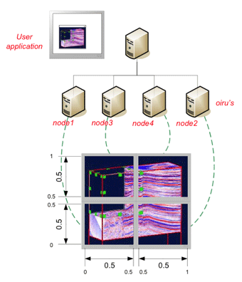
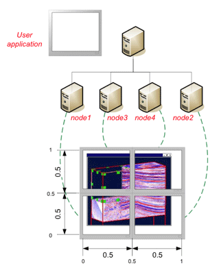
A tiled display configuration is usually used to describe a large flat (or nearly flat) display forming a larger 2D virtual graphics window.
A tiled display allows you to have a physically larger image which is still high resolution (pixels per inch). Stated more simply, a tiled display gives you an image containing more pixels (as opposed to using a projector, which can produce a physically larger image but with lower resolution). The benefit of this is that it is possible to see more details in the rendered image, particularly in the case of very large data sets.
Flat screen configurations are well suited for presentations targeted to a larger audience, e.g., presentations in a seminar room or in a lecture hall. Such configurations can be defined easily and are not intended to be used with a tracking system (for info on head tracking and immersive interaction (see the section called “Tracking support”).
To define this type of configuration you must use SoFlatScreen SoFlatScreen SoFlatScreen nodes in your cluster configuration file.
The application runs locally as usual, i.e., the scene graph is traversed and rendered locally, as it would be on a standalone machine. In addition, the scene graph is distributed on the cluster and all scene graph changes are synchronized on all cluster render nodes, allowing them to render their viewport on their display.
Example 3.3. A 2x2 tiled display
#ScaleViz V7.0 ascii

  ScaleVizConfig
    {
    name "4 FlatScreen" MasterConfig
      {
      hostname "master"
      }
    FlatScreen
      {
        hostname "node1"
        tileSize 0.5 0.5
        tileOrigin 0.0 0.0
      }
    FlatScreen
      {
        hostname "node2"
        tileSize 0.5 0.5
        tileOrigin 0.5 0.0
      }
    FlatScreen
      {
        hostname "node3"
        tileSize 0.5 0.5
        tileOrigin 0.0 0.5
      }
    FlatScreen
      {
        hostname "node4"
        tileSize 0.5 0.5
        tileOrigin 0.5 0.5
      }
    }
In the configuration described in Example 3.3, “ A 2x2 tiled display” the application is launched on the master of the graphics cluster like it would be on a single machine. As a result, scene manipulation/interaction is done in the application on the master node, the same way as usual, i.e., like it would be on a single machine. Note that the channelSize and channelOrigin fields were not needed because we wanted to use the entire screen on each render node.
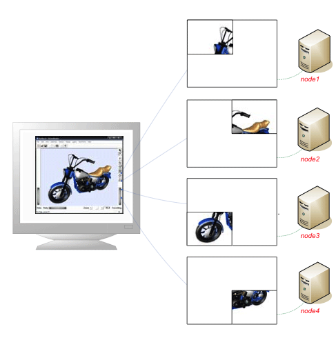
Example 3.4. A 2x2 tiled display with edge overlap support
#ScaleViz V7.0 ascii

  ScaleVizConfig
    {
    MasterConfig
      {
      hostname "master"
      }
    FlatScreen
      {
        hostname "node1"
        channelSize 1280 1024
        channelOrigin 0 0
        softEdgeOverlap 0 45 0 53
      }
    FlatScreen
      {
        hostname "node2"
        channelSize 1280 1024
        channelOrigin 0 0
        softEdgeOverlap 45 0 0 53
      }
    FlatScreen
      {
        hostname "node3"
        channelSize 1280 1024
        channelOrigin 0 0
        softEdgeOverlap 0 45 53 0
      }
    FlatScreen
      {
        hostname "node4"
        channelSize 1280 1024
        channelOrigin 0 0
        softEdgeOverlap 45 0 53 0
      }
    }
This example shows how to specify edge overlaps. This avoids rendering artifacts caused by the fact that the pixels of adjacent screens are not physically adjacent. The softEdgeOverlap field specifies the number of pixels that would be “hidden” by the screen borders if the screens were physically adjacent underneath the screen borders. The overlap values are specified in the following order: left, right, bottom, top.
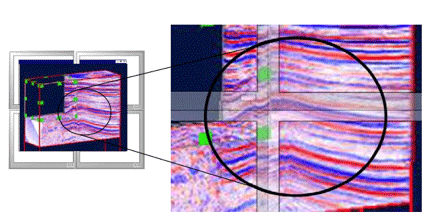
Parts of the image are “hidden” by the screen borders
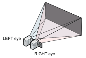
To define a passive stereo tiled display configuration, you must use SoFlatScreen SoFlatScreen SoFlatScreen and set the cameraMode field to the appropriate value LEFT_VIEW or RIGHT_VIEW instead of the default MONOSCOPIC value.
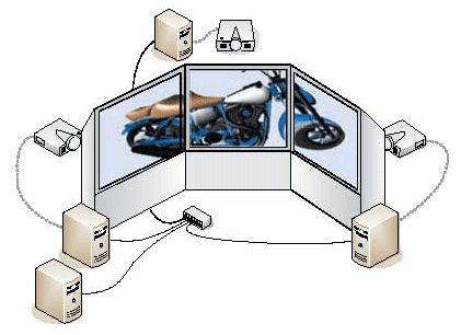
Tile compositing configurations allow decomposition of the application viewer’s viewport into several parts that will be rendered independently by different render nodes, then composited into a single image.
Since each render unit does rendering of its sub-viewport in parallel, this configuration allows increased fill rate and/or level of detail for VolumeViz LDM-based modules (due to having a smaller numbers of pixels to render but still having access to all of the system memory and the GPU texture memory).
On the application side, there is no traversal of the scene graph for rendering: the sub-frames rendered by the OIRU are simply received and displayed as is (after decompression if needed).
Distribution of the viewport across render units is specified through the tileOrigin and tileSize fields of SoTileComposer SoTileComposer SoTileComposer nodes.
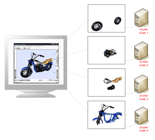
Example 3.6. Tile compositing mode applied to the harley.iv example model using 4 render units
#ScaleViz V7.0 ascii

  ScaleVizConfig
    {
    name "4 TileComposer"
      MasterConfig
      {
        hostname "masterNode"
        port 3456
      }
    TileComposer
      {
        hostname node1
        tileOrigin 0.0 0.0
        tileSize 0.5 0.5
      }
    TileComposer
      {
        hostname node2
        tileOrigin 0.5 0.0
        tileSize 0.5 0.5
      }
    TileComposer
      {
        hostname node3
        tileOrigin 0.0 0.5
        tileSize 0.5 0.5
      }
    TileComposer
      {
        hostname node4
        tileOrigin 0.5 0.5
        tileSize 0.5 0.5
      }
    }
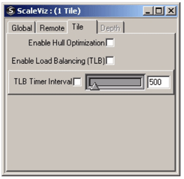
To keep the performance as stable as possible, ScaleViz provides the capability to perform load balancing. Depending on the workload of each OIRU, ScaleViz will dynamically calculate (and change if necessary) the viewport size in order to redistribute the workload when one or more OIRUs becomes overloaded.
To use this feature, the field enableLoadBalancing (tile load balancing) must be set to TRUE in the SoTileComposerParams SoTileComposerParams SoTileComposerParams node of the ScaleViz configuration. Activating the tile load balancing feature forces ScaleViz to check periodically if any of the OIRUs are overloaded. The amount of time between two checks is set by default to 500ms. This value can be changed using the loadBalancingInterval field of the SoTileComposerParams SoTileComposerParams SoTileComposerParams node
Here is an example of ScaleViz configuration activating the tile load balancing
#ScaleViz V7.0 ascii

  ScaleVizconfig
    {

    SoScaleVizParameters
      {

      tileComposerParams SoTileComposerParams
        {
          enableLoadBalancing TRUE
          loadBalancingInterval 200
        }
      }
    ...
    }
|
Depth compositing configurations allow decomposition of an application viewer’s scene graph into several parts that will be rendered independently by different render nodes using the full viewer viewport. A compositing step between the nodes recomposes the full frame depending on the depth value of each pixel.
As each render unit does rendering of its sub-scene graph in parallel, this configuration is very useful for managing scene graphs with very large geometry, i.e., having large numbers of triangles.
No scene graph rendering traversal is done on the application side: the sub-frames rendered by the OIRU are simply received and displayed as is (after decompression if needed).
Scene graph distribution points can be set with SoSeparator SoSeparator SoSeparator (and derived classes) and SoVRMLGroup SoVRMLGroup SoVRMLGroup (and derived classes) nodes, using the renderUnitId fields.
The renderUnitId field specifies to which render unit the scene graph below the SoSeparator SoSeparator SoSeparator or SoVRMLGroup SoVRMLGroup SoVRMLGroup will be dispatched. This property is only used in depth compositing mode and local compositing described in the next section, and is not taken into account when using other cluster configurations (FlatScreen, TileComposer …).
The renderUnitId can be controlled in different ways:
By setting the renderUnitId field of specific separators in the Open Inventor scene graph.
At runtime with the help of the ivTuneViewer tool. Remember to save your modified scene graph in a file for later reuse.
Automatically with SoDistributeAction.
By overriding the virtual method SoNode::getRenderUnitID(). This is described in the the section called “Local compositing”.
Possible values and meanings for renderUnitId are:
-1 | (SO_RENDERUNITID_NONE) This SoSeparator SoSeparator SoSeparator node is not distributed to any of the render nodes. |
-2 | (SO_RENDERUNIT_INHERIT) The renderUnitId is inherited from the parent’s renderUnitId. Default. |
-3 | (SO_RENDERUNIT_ALL) This SoSeparator SoSeparator SoSeparator node is distributed to all render nodes. |
1...N | This SoSeparator SoSeparator SoSeparator node is distributed to the specified render unit ID modulo the number of render units actually available. That is: RenderUnitUsed = ((renderUnitId-1)%(ActualNumberOfRenderUnits))+1 |
0 | Local rendering is done on the application side only. The localCompositing field of SoScaleVizParameters SoScaleVizParameters SoScaleVizParameters node must be set to TRUE (see the section called “Local compositing”). |
| |
The default value of the renderUnitId field is -2 (SO_RENDERUNIT_INHERITID), which means that the subgraph is not distributed to any node, unless a parent separator has set a different value for renderUnitId. In other words, in order to use depth compositing, you must modify renderUnitId from the default, otherwise nothing will be rendered. |
Setting the renderUnitId field to -3 is useful in some circumstance. For example:
Rendering of nodes that disable the depth buffer. In this case the depth value is undefined and thus cannot be composited correctly. SoGradientBackground SoGradientBackground SoGradientBackground is a good example.
Nodes that work on the resulting frame buffer using an SoRenderToTextureProperty node to do filtering/compression.
Some pre-distributed scene graph examples are available in the following directory:
$OIVHOME/data/ScaleViz/models/distributed/
The main principle of preparing a scene graph for distribution is to think about how to divide up the scene graph to obtain a good load balance between all render nodes.
![[Tip]](../../images/tip.jpg) | |
Depending on the number of render units that are available in your cluster, you might need to split your shapes into smaller shapes. Please refer to the paragraph the section called “ Split Geometry Action”, to learn more. |
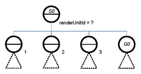
At startup and before any scene graph processing for distribution, a scene graph looks like the following:

Suppose now that for each scene graph branch, the load is balanced. For instance, there are two million triangles per branch. The best assignment of renderUnitIds is as follows:

If the total number of render units in the cluster is greater than or equal to the number of renderUnitId s referenced in the scene graph, each branch of the scene graph will be rendered by one (or none) of the available render units. If the total number of render units in the cluster is less than the number of renderUnitId s assigned, the branches will be assigned to render units depending on the renderUnitId field modulo the total number of render units. The render unit will traverse all paths containing a separator with the matching renderUnitId.
| |
By default renderUnitId is inherited (set to -2, SORENDERUNITID_INHERIT). Therefore it is only necessary to specify the renderUnitId field at distribution points. |
Along the same lines, one can imagine preparing a scene graph to be ready to support different cluster configurations: for example, the same scene graph can be ready for a 2-unit rendering cluster and/or for a maximum configuration using a 5-unit rendering cluster. This can be done easily by assigning distribution points in the scene graph.
The following figures illustrate how render units can be assigned to ensure reasonably good load balancing independent of the total number of render nodes.
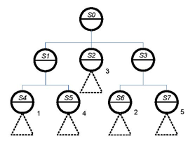
If the load is well balanced between the sub-graphs (S2, S4, S5, S6, S7), running with 5 render units will provide the best performance.
Nevertheless, the scene graph distribution is also well designed to be used with 3 render units.
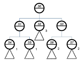
If there are only 3 render nodes, the previous scene graph is automatically distributed by ScaleViz depending on the modulo computation. And reasonable load balancing can still be achieved.
Exception to the above discussion:
Let’s consider again the previous scene graph example, except this time we add a new sub-graph under a group node.
Remember that the renderUnitId field is part of the SoSeparator SoSeparator SoSeparator node. Thus, as the normal work of SoSeparator SoSeparator SoSeparator nodes, the renderUnitId property does not apply to the parent node.
Therefore, the group node G0 inherits the renderUnitId property from S0:
If S0 value is -1, S0 will not be traversed.
If S0 value is -2, G0 will not be rendered.
If S0 value is -3, G0 will be rendered by all render nodes.
If S0 value is [1...n], the rendering of G0 will be done by the specified render unit.
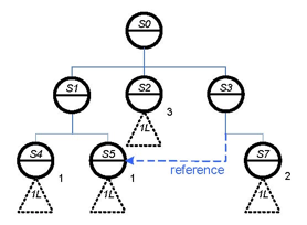
Therefore, you should be careful with nodes that are referenced more than once in your scene graph. In the example to the left, node S5 is rendered by render unit 1 in the two paths [S0, S1, S5] and [S0, S3, S5]. The rendering load for render unit 1 is thus three times larger than on render units 2 and 3.
In order to simplify the distribution of the scene graph, ScaleViz supports two different algorithms for the automatic allocation of render unit IDs of each separator in a scene graph. These distribution algorithms are accessible via the Open Inventor class SoDistributeAction SoDistributeAction SoDistributeAction .
ROUND_ROBIN, which implements a round robin algorithm, does static allocation based on the number of running OIRUs. This algorithm is the fastest way to distribute a scene graph between all running OIRUs, but as it does not take in account the weight of the sub scene graph assigned to each OIRU, it can potentially result in an unbalanced distribution.
TRIANGLE_COUNT is dynamic algorithm that takes in account the weight of each separator, and tries to distribute the scene graph as equally as possible between OIRUs. Compared with the first algorithm, it’s more time consuming, but the result is a better balanced scene graph distribution.
To specify the desired distribution algorithm, use Open Inventor action SoDistributeAction. All you you need to do is instantiate an SoDistributeAction, specify the the desired algorithm, and apply the action on the scene graph that you want to distribute.
Local compositing allow you to force a part of a scene graph to be render on the application machine while another part of it is rendered remotely by the cluster.
This is particularly useful when an application uses custom nodes that depend on being part of the application process or uses SoCallback SoCallback SoCallback nodes that make direct OpenGL calls. Another interesting scenario is the combined visualization of remote data with data created or loaded locally, in order to avoid sending this data to the cluster. Local compositing is available for tile or depth compositing mode. The localCompositing field of the SoScaleVizParameters SoScaleVizParameters SoScaleVizParameters node in a ScaleViz configuration scene graph should be set to TRUE.
There are two ways to indicate that a node or group of node should be rendered locally:
First, by explicitly setting a renderUnitId=0 directly in an SoSeparator node. All of the children of this separator will be rendered locally
The second way is to specify that all instances of a custom node must be rendered locally. This can be done by overriding the virtual function SoNode::getRenderUnitID() for this node class. This function returns the preferred renderUnitId that should be used for rendering. When this type of node is traversed, the closest parent separator will replace its own renderUnitId field value with the value returned by this function if the returned value has a higher priority than its own.
The priority order is as follows:
SO_RENDERUNITID_NONE (-1)
0 (render locally)
SO_RENDERUNITID_ALL (-3)
x>0 (render on the specified OIRU)
SO_RENDERUNITID_INHERIT (-2)
with SO_RENDERUNITID_NONE having the highest priority and SO_RENDERUNITID_INHERIT the lowest.
Example:
All nodes that do not modify the depth buffer during normal render traversal values should return SO_RENDERUNITID_ALL or 0 in depth compositing mode. For example, SoAnnotation SoAnnotation SoAnnotation nodes override the getRenderUnitId() method and return SO_RENDERUNITID_ALL when compositing is enabled. Therefore if its parent SoSeparator SoSeparator SoSeparator has a value of:
0 Rendering is done locally (0 has a higher priority than SO_RENDERUNITID_ALL)
2 Rendering is done on all nodes (because SO_RENDERUNITID_ALL has a higher priority)
As described earlier, ScaleViz is based on distribution of the scene graph. Open Inventor actions need to traverse the scene graph and if the scene graph is distributed, a standard action won’t be able to access the whole scene graph but only the part rendered locally. For this reason, ScaleViz now provides some extended actions, which can be applied to a distributed scene graph and execute in parallel on the render nodes (OIRUs). These actions include support for asynchronous execution of the action.
The following actions are distributed version of standard Open Inventor actions:
ScGetPrimitiveCountAction is the distributed version of SoGetPrimitiveCountAction
ScGetBoundingBoxAction is the distributed version of SoGetBoundingBoxAction
ScRayPickAction is the distributed version of SoRayPickAction
These actions can either be:
Synchronous: action is distributed across the cluster but the call to the apply() method will block until all OIRUs send the result of the action.
Asynchronous: the application is notified, through a user defined callback, when the result of the action is available.
Distributed actions are used in the same way as the corresponding standard actions of Open Inventor. An action is instantiated and the apply() method is used to launch the action on the selected node.
The arguments passed to a distributed action are the same as for the corresponding standard action. Only three new parameters are required in the case of a distributed action:
A pointer to the callback function
An optional pointer to user data
The distribution mode which can be either Local Only, Cluster Only, or All (meaning the action is respectively executed only locally, only on the OIRU, or on the OIRU and locally)
A distributed action is synchronous or asynchronous based on the callback pointer. If you create a distributed action and set the callback pointer to NULL, the action will be synchronous. Otherwise, if the callback is defined, the action will be asynchronous.
A coding example can be found in $OIVHOME/ScaleViz/examples/DistributedAction. For more information on the distributed actions, please see the Reference Manual.
ScaleViz parameters are dynamically accessible through the ScaleViz GUI dialog. This tabbed dialog allows you to set the parameters described in previous sections, providing an easy way for you to test and experiment with all ScaleViz features at runtime.
This dialog is accessible only if you are using SoWinViewer SoWinViewer , SoQtViewer , or SoXtViewer or one of their derived classes. It can be displayed by pressing SHIFT+F9.
You can specify another shortcut key sequence by setting SCALEVIZ_GUI_SHORTCUT in your Open Inventor configuration file. The use of the ScaleViz GUI dialog can be entirely disabled by setting the SCALEVIZ_DISABLE_GUI environment variable to 1. In this case, connection, disconnection, parameter setting, etc. must be done programmatically.
| |
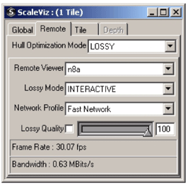
In addition to allowing parameter changes, the ScaleViz GUI dialog shows the current frame rate and network bandwidth used when doing remote rendering. |
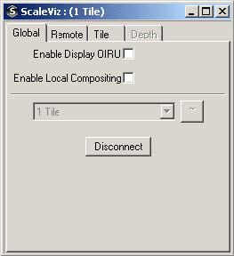
The following pages show screenshots of the tabs, and indicate which field is associated with each widget. Note that screenshots have been taken from a Windows environment, but the main layout is the same for all supported platforms.
|
Widget Label |
Widget Type |
Associated Field |
|---|---|---|
|
Enable Display OIRU |
CheckBox |
displayOIRU |
|
Enable Local Compositing |
CheckBox |
localCompositing |
|
Widget Label |
Widget Type |
Associated Field |
|---|---|---|
|
Hull Optimization Mode |
ComboBox |
hullOptimization |
|
Lossy Mode |
ComboBox |
lossyMode |
|
NetWork Profile |
ComboBox |
networkSpeed |
|
Lossy Quality |
Slider |
lossyQuality |
On this tab, the parameter modifications are applied to the selected viewer (the unique identifier of the selected viewer appears in the ComboBox named Remote Viewer)
|
Widget Label |
Widget Type |
Associated Field |
|---|---|---|
|
Enable Hull Optimization |
CheckBox |
hullOptimization |
|
Enable Load Balancing |
ComboBox |
enableLoadBalancing |
|
TLB Timer Interval |
Slider |
loadBalancingInterval |
|
Widget Label |
Widget Type |
Associated Field |
|---|---|---|
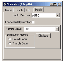
|
Depth Precision |
ComboBox |
depthBits |
|
Enable Hull Optimization |
CheckBox |
hullOptimization |
|
Distribution Method |
Radio Button |
Sets the distributeMethod method property of SoDistributeAction |
On this tab, the parameter modifications are applied to the selected viewer (the unique identifier of the selected viewer appears in the ComboBox named Remote Viewer)
This section presents a way to test and experience most of the ScaleViz features with your application running on a workstation. In this scenario, all threads are launched locally and then all hardware resources are used concurrently. Although the observed performance will not be representative of what you would obtain using a real cluster, running ScaleViz locally is still a good way to experiment and get a general overview of the ScaleViz functionality without having to install a cluster.
Here are the few steps to follow:
Set the OIV_CONFIG_FILE environment variable to $OIVHOME/data/ScaleViz/oiv-scaleviz.cfg.
Launch the ScaleViz daemon by using default parameters (see the section called “Starting / Stopping the ScaleViz Daemon”).
Launch your application, and press the SHIFT + F9 keys.
Select the desired configuration (see Section 3.2.3, “Application Setup” for details on different configurations).
Click on the “connect” button to allow your application connect to the daemon, and then to the OIRU. (For more details, see the section called “ Connection and disconnection”).
To test another configuration, just click on disconnect button, select another configuration, and then click on “connect” button.
Once connected, your application will be running in ScaleViz mode. Several windows may appear, each corresponding to the render area of each OIRU.
By default all viewers derived from SoXtRenderArea , SoQtRenderArea , or SoWinRenderArea SoWinRenderArea are synchronized. However, it is sometimes useful to disable remote rendering of a certain viewer used for very simple rendering. For example, using the cluster is not useful for rendering the color editor.
You can disable the viewer synchronization through the sync parameter of the viewer constructor. See the Reference Manual for more details.
While the tiled display configuration defined by SoFlatScreen SoFlatScreen SoFlatScreen nodes is used to visualize a large flat screen, ScaleViz allows a more general way to define display configuration since screens can be defined in a 3D world. For example, the screens can be arranged perpendicular to each other like in a CAVE or a Holobench. Any arrangement can be defined. However, a general configuration may be complex to configure. The exact location of the screens must be known in this case. Immersive configurations are defined using the SoScreen SoScreen SoScreen nodes.
A typical configuration file for an immersive display could be:
#ScaleViz V7.0 ascii

  ScaleVizConfig
    {
    name "4 Screen"
      MasterConfig
      {
        hostname "masterNode"
        port 3456
      }

    Screen
      {
        hostname "node1"
        lowerLeft -10 -10 -10
        lowerRight 10 -10 -10
        upperLeft -10 10 -10
      }
    Screen
      {
        name "node2"
        lowerLeft -10 -10 10
        lowerRight 10 -10 10
        upperLeft -10 -10 -10
      }
    Screen
      {
        name "node3"
        lowerLeft -10 -10 10
        lowerRight -10 -10 -10
        upperLeft -10 10 10
      }
    Screen
      {
        name "node4"
        lowerLeft 10 -10 -10
        lowerRight 10 -10 10
        upperLeft 10 10 -10
      }

    Tracker
      {
        server "4147:4148"
        defaultCameraPosition 0.0 0.0 10.0
        defaultObjectPosition 0.0 0.0 0.0
        defaultObjectBoxMaxDim 1.0
      }
    }
| |
Passive stereo is supported using the cameraMode field of SoFlatScreen (seethe section called “ScaleViz Passive Stereo Tiled Display Configuration”). |
Tracking is used for head tracking and interaction in an immersive environment with input devices such as a wand. The ScaleViz extension provides a default behavior that assumes the use of a wand and two tracker sensors (one for the head and one for the wand). This default behavior is customizable and can be easily adapted to almost any kind of tracking and input devices.
By default, ScaleViz uses trackd from VRCO to interface with the tracking system. trackd is not part of Open Inventor. It must be purchased and installed separately. For more information about this product, please see www.vrco.com.
Before a tracking system can be used with the ScaleViz extension, the trackd daemon (and possibly a trackd server) must be started. The trackd daemon connects to the tracking system and provides the actual tracker and controller data in two shared memory segments which are read by ScaleViz.
ScaleViz provides a set of classes similar to the trackdAPI™ classes. ScaleViz has a built-in interface to trackd that does not require the application to be built with trackdAPI™ libraries. trackdAPI™ is dynamically loaded when the constructor of the classesSoTrackerReader SoTrackerReader SoTrackerReader an d SoControllerReader SoControllerReader SoControllerReader is called. These classes provide:
Convenience functions that return tracking data in Open Inventor data types.
Dynamic loading of the trackd library into memory at runtime, so there is no dependence of the application on trackd.
Ability for the programmer to provide a transformation matrix to convert raw coordinates from the tracker into Open Inventor coordinates.
Information about changes in button states.
A unit conversion mechanism (considering that trackd returns all tracker coordinates in feet).
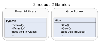
Custom nodes will not work as-is in a cluster rendering environment. Custom nodes in the scene graph will be copied to the render computers, but the OIRU code does not contain the implementation of these nodes. The OIRU is able to dynamically load implementations of custom nodes, but a small amount of additional work is needed to enable this capability. It is necessary to build the custom nodes as one or more shared libraries/DLLs separate from the application.
Creating new nodes, each in its own library, is described in The Inventor Toolmaker. Some examples can be found in the $OIVHOME/Inventor/examples/ToolMaker directory. On Windows, see ToolMaker/02.NodesDLL. In this case, Open Inventor will dynamically load files named pyramid.so and glow.so (pyramid.dll and glow.dll on Windows) and automatically call the initClass method
Starting with Open Inventor 7.0, loading of custom nodes has been extended to support shared libraries defining a set of custom nodes. Shared libraries must be specified by the OIV_USER_LIBS environment variable, which is a semi-colon separated list of shared libraries (UNIX) or DLLs (Windows) that contain custom nodes to be loaded. Libraries in the list can be specified with a full path, relative path, or no path. Libraries can be defined without any extension, thus allowing portability of the environment variable.
An example of OIV_USER_LIBS definition:
OIV_USER_LIBS $HOME/myLib2;myLib2.so;../../../myLib2
Open Inventor will search for custom node initClass() method in a ll specified directories as described in SoDynamicLibManager (see the section called “ Dynamic Library Management”).
Open Inventor loads a custom node as follows:
If you encounter problems while loading custom nodes, you can set the IV_DEBUG_FROMNAME environment variable to 1. Open Inventor will output the status of each loading step for each custom node encountered.
The following features are not supported in cluster rendering mode in ScaleViz 7.0:
Mixing multipipe and cluster rendering is not supported
Use of SoCallback SoCallback SoCallback nodes is not supported.
Mixing tile composition and depth composition is not supported.
Stereoscopy:
The interlaced and half-screen stereoscopy modes supported by standalone Open Inventor viewers are not supported by ScaleViz.
The active stereoscopy mode is not supported by ScaleViz (“raw” OpenGL quad-buffered stereo).
However the passive stereoscopy mode with separate displays or projectors sets for left and right eyes is supported by ScaleViz.