The marker node, SoMarkerSet SoMarkerSet SoMarkerSet , represents a set of bitmaps located at the coordinates specified by the vertexProperty field (from SoVertexShape SoVertexShape SoVertexShape ) or the current inherited coordinates. For optimal performance, use of the vertexProperty field is recommended.
SoMarkerSet SoMarkerSet SoMarkerSet uses the coordinates in order, starting with the first. The number of markers in the set is specified by the numPoints field. The coordinates of the marker set are transformed by the current cumulative transformation.
You set the bitmap to be drawn at each point using the field markerIndex, which indexes into the list of defined bitmaps. The enumeration SoMarkerSet::MarkerType defines the list of predefined markers.
Defining new markers:
The following method allows users to add new markers which are not available in the list of predefined markers:
void addMarker(int markerIndex,
               const SbVec2s &size,
               const unsigned char *bytes,
               SbBool isLSBFirst = TRUE,
               SbBool isUpToDown = TRUE)
void AddMarker(int markerIndex,
               SbVec2s size,
               byte[] bytes,
               bool isLSBFirst,
               bool isUpToDown)
void addMarker(int markerIndex,
	           SbVec2s size,
	           byte[] bytes,
	           boolean isLSBFirst,
	           boolean isUpToDown)
markerIndex is the index of the new marker (if this marker already exists, it is replaced by the new one), size is the width and height of the bitmap in pixels, and bytes is the array containing the bitmap. The bitmap is arranged row-by-row, from left to right, and down to up (or up to down according to the parameter isUpToDown). Each byte corresponds to eight pixels.
If isLSBFirst is TRUE, bits are ordered within a byte from least significant to most significant; otherwise the first bit in each byte is the most significant one. If isUpToDown is TRUE, the marker bitmap is described from up to down (that is bytes [0] is the left top corner of the bitmap), otherwise from down to up (that is bytes [0] is the bottom left corner).
Example 5.10. How to use SoMarkerSet
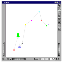
This example displays a marker set composed of predefined markers and new markers using the SoMarkerSet SoMarkerSet SoMarkerSet node. The source code is available in:
$OIVHOME/src/Inventor/examples/Features/MarkerSet/markerSet.cxx.
int
main(int argc, char **argv)
{
  // Initialize Inventor and Xt
  Widget myWindow = SoXt::init(argv[0]);

  // Array containing the coordinates
  // of the markers.
  SbVec3f markersCoords[NUM_MARKERS]=
    {
    SbVec3f(0.5,0.5,0), SbVec3f(1.5,3.8,0), SbVec3f(1.8,1.2,0), SbVec3f(2.4,1.9,0),
      SbVec3f(3.2,6.3,0), SbVec3f(4.5,7.2,0), SbVec3f(6.3,9.3,0), SbVec3f(6.9,7.2,0),
      SbVec3f(8.0,6.0,0), SbVec3f(8.5,6.3,0)
    };
  };

  // Array containing the colors of the markers.
  SbColor markersColors[NUM_MARKERS]=
    {
    SbColor(1,0,0), SbColor(0,1,0), SbColor(0,0,1), SbColor(1,1,1), SbColor(1,1,0),
      SbColor(1,0,1), SbColor(0,1,1), SbColor(1,0,0), SbColor(0,1,0), SbColor(0,0,1)
    };
  };

  // Array containing the indices of the markers.
  int markersIndexes[NUM_MARKERS]=
    {
    90, 91, 92, SoMarkerSet::CIRCLE_FILLED_9_9,
      SoMarkerSet::SQUARE_FILLED_9_9,
      SoMarkerSet::DIAMOND_FILLED_9_9, SoMarkerSet::TRIANGLE_FILLED_9_9,
      SoMarkerSet::RHOMBUS_FILLED_9_9, SoMarkerSet::HOURGLASS_FILLED_9_9
    };

  // Array containing a new marker "arrow"
  static unsigned char arrowBits[] =
  {
  0x00, 0xff, 0xff, 0x01, 0x00, 0x00, 0xff, 0xff, 0x01, 0x00, 0x00,
    0xff, 0xff, 0x01, 0x00, 0x00, 0xff, 0xff, 0x01, 0x00, 0x00, 0xff,
    0xff, 0x01, 0x00, 0x00, 0xff, 0xff, 0x01, 0x00, 0x00, 0xff, 0xff,
    0x01, 0x00, 0x00, 0xff, 0xff, 0x01, 0x00, 0x00, 0xff, 0xff, 0x01,
    0x00, 0x00, 0xff, 0xff, 0x01, 0x00, 0x00, 0xff, 0xff, 0x01, 0x00,
    0x00, 0xff, 0xff, 0x01, 0x00, 0x00, 0xff, 0xff, 0x01, 0x00, 0x00,
    0xff, 0xff, 0x01, 0x00, 0x00, 0xff, 0xff, 0x01, 0x00, 0x00, 0xff,
    0xff, 0x01, 0x00, 0x00, 0xff, 0xff, 0x01, 0x00, 0x00, 0xff, 0xff,
    0x01, 0x00, 0x00, 0xff, 0xff, 0x01, 0x00, 0x00, 0xff, 0xff, 0x01,
    0x00, 0x00, 0xff, 0xff, 0x01, 0x00, 0x00, 0xff, 0xff, 0x01, 0x00,
    0xff, 0xff, 0xff, 0xff, 0x01, 0xff, 0xff, 0xff, 0xff, 0x01, 0xfe,
    0xff, 0xff, 0xff, 0x00, 0xf8, 0xff, 0xff, 0x3f, 0x00, 0xe0, 0xff,
    0xff, 0x0f, 0x00, 0xc0, 0xff, 0xff, 0x03, 0x00, 0x00, 0xff, 0xff,
    0x01, 0x00, 0x00, 0xfc, 0x7f, 0x00, 0x00, 0x00, 0xf8, 0x1f, 0x00,
    0x00, 0x00, 0xe0, 0x07, 0x00, 0x00, 0x00, 0x80, 0x01, 0x00, 0x00
  };
  // Array containing a new marker "target"
  static unsigned char targetBits[] =
  {
  0xe0, 0x0f, 0x00, 0x18, 0x31, 0x00, 0x04, 0x41, 0x00, 0xc2, 0x87,
    0x00, 0x22, 0x89, 0x00, 0x11, 0x11, 0x01, 0x09, 0x21, 0x01, 0x09,
    0x21, 0x01, 0xff, 0xff, 0x01, 0x09, 0x21, 0x01, 0x09, 0x21, 0x01,
    0x11, 0x11, 0x01, 0x22, 0x89, 0x00, 0xc2, 0x87, 0x00, 0x04, 0x41,
    0x00, 0x18, 0x31, 0x00, 0xe0, 0x0f, 0x00
  };

  // Array containing a new marker "tgs"
  static unsigned char tgsBits[] =
  {
  0xff, 0xff, 0x1f, 0x00, 0x00, 0x00, 0x1f, 0x1f, 0x1f, 0x04, 0x11,
    0x11, 0x04, 0x01, 0x01, 0x04, 0x1d, 0x1f, 0x04, 0x11, 0x10, 0x04,
    0x11, 0x11, 0x04, 0x1f, 0x1f, 0x00, 0x00, 0x00, 0xff, 0xff, 0x1f
  };

  // Add the new markers.
  SoMarkerSet::addMarker(90, SbVec2s(17, 17), targetBits);
  SoMarkerSet::addMarker(91, SbVec2s(33, 33), arrowBits);
  SoMarkerSet::addMarker(92, SbVec2s(21, 11), tgsBits);

  SoSeparator *root = new SoSeparator;

  root->ref();

  // Sets the coordinates of the markers.
  SoCoordinate3 *coords = new SoCoordinate3;
  coords->point.setValues(0, NUM_MARKERS, markersCoords);

  // Sets the indices of the markers.
  SoMarkerSet *markerSet = new SoMarkerSet;
  markerSet->markerIndex.setValues(0, NUM_MARKERS, markersIndexes);

  SoMaterialBinding *matBind = new SoMaterialBinding;
  matBind->value = SoMaterialBinding::PER_VERTEX;

  // Sets the color of the markers.
  SoMaterial *mat = new SoMaterial;
  mat->diffuseColor.setValues(0, NUM_MARKERS, markersColors);

  root->addChild(coords);
  root->addChild(new SoLineSet);
  root->addChild(matBind);
  root->addChild(mat);
  root->addChild(markerSet);

  // Create a viewer
  SoXtExaminerViewer *myViewer;
  myViewer = new SoXtExaminerViewer(myWindow);

  // Attach and show viewer
  myViewer->setSceneGraph(root);
  myViewer->setTitle("Marker");
  myViewer->setSize(SbVec2s(554, 380));

  myViewer->show();
  myViewer->viewAll();

  // Loop forever
  SoXt::show(myWindow);
  SoXt::mainLoop();
  return 0;
}
// Array containing the coordinates of the markers.
SbVec3f[] markersCoords = new SbVec3f[NUM_MARKERS]
{
  new SbVec3f(0.5f, 0.5f, 0.0f), new SbVec3f(1.5f, 3.8f, 0.0f),
  new SbVec3f(1.8f, 1.2f, 0.0f), new SbVec3f(2.4f, 1.9f, 0.0f),
  new SbVec3f(3.2f, 6.3f, 0.0f), new SbVec3f(4.5f, 7.2f, 0.0f),
  new SbVec3f(6.3f, 9.3f, 0.0f), new SbVec3f(6.9f, 7.2f, 0.0f),
  new SbVec3f(8.0f, 6.0f, 0.0f), new SbVec3f(8.5f, 6.3f, 0.0f)
};

// Array containing the colors of the markers.
SbColor[] markersColors = new SbColor[NUM_MARKERS]
{
  new SbColor(1,0,0), new SbColor(0,1,0),
  new SbColor(0,0,1), new SbColor(1,1,1),
  new SbColor(1,1,0), new SbColor(1,0,1),
  new SbColor(0,1,1), new SbColor(1,0,0),
  new SbColor(0,1,0), new SbColor(0,0,1)
};

// Array containing the indices of the markers.
int[] markersIndexes = new int[NUM_MARKERS]
{
  90, 91, 92, (int)SoMarkerSet.MarkerTypes.CIRCLE_FILLED_9_9,
  (int)SoMarkerSet.MarkerTypes.SQUARE_FILLED_9_9,
  (int)SoMarkerSet.MarkerTypes.DIAMOND_FILLED_9_9,
  (int)SoMarkerSet.MarkerTypes.TRIANGLE_FILLED_9_9,
  (int)SoMarkerSet.MarkerTypes.RHOMBUS_FILLED_9_9,
  (int)SoMarkerSet.MarkerTypes.HOURGLASS_FILLED_9_9, 0
};

// Array containing a new marker ()"arrow"
byte[] arrowBits = new byte[]
{
  0x00, 0xff, 0xff, 0x01, 0x00, 0x00, 0xff, 0xff, 0x01, 0x00, 0x00, 0xff,
  0xff, 0x01, 0x00, 0x00, 0xff, 0xff, 0x01, 0x00, 0x00, 0xff, 0xff, 0x01,
  0x00, 0x00, 0xff, 0xff, 0x01, 0x00, 0x00, 0xff, 0xff, 0x01, 0x00, 0x00,
  0xff, 0xff, 0x01, 0x00, 0x00, 0xff, 0xff, 0x01, 0x00, 0x00, 0xff, 0xff,
  0x01, 0x00, 0x00, 0xff, 0xff, 0x01, 0x00, 0x00, 0xff, 0xff, 0x01, 0x00,
  0x00, 0xff, 0xff, 0x01, 0x00, 0x00, 0xff, 0xff, 0x01, 0x00, 0x00, 0xff,
  0xff, 0x01, 0x00, 0x00, 0xff, 0xff, 0x01, 0x00, 0x00, 0xff, 0xff, 0x01,
  0x00, 0x00, 0xff, 0xff, 0x01, 0x00, 0x00, 0xff, 0xff, 0x01, 0x00, 0x00,
  0xff, 0xff, 0x01, 0x00, 0x00, 0xff, 0xff, 0x01, 0x00, 0x00, 0xff, 0xff,
  0x01, 0x00, 0xff, 0xff, 0xff, 0xff, 0x01, 0xff, 0xff, 0xff, 0xff, 0x01,
  0xfe, 0xff, 0xff, 0xff, 0x00, 0xf8, 0xff, 0xff, 0x3f, 0x00, 0xe0, 0xff,
  0xff, 0x0f, 0x00, 0xc0, 0xff, 0xff, 0x03, 0x00, 0x00, 0xff, 0xff, 0x01,
  0x00, 0x00, 0xfc, 0x7f, 0x00, 0x00, 0x00, 0xf8, 0x1f, 0x00, 0x00, 0x00,
  0xe0, 0x07, 0x00, 0x00, 0x00, 0x80, 0x01, 0x00, 0x00
};

// Array containing a new marker ()"target"
byte[] targetBits = new byte[]
{
  0xe0, 0x0f, 0x00, 0x18, 0x31, 0x00, 0x04, 0x41, 0x00, 0xc2, 0x87, 0x00,
  0x22, 0x89, 0x00, 0x11, 0x11, 0x01, 0x09, 0x21, 0x01, 0x09, 0x21, 0x01,
  0xff, 0xff, 0x01, 0x09, 0x21, 0x01, 0x09, 0x21, 0x01, 0x11, 0x11, 0x01,
  0x22, 0x89, 0x00, 0xc2, 0x87, 0x00, 0x04, 0x41, 0x00, 0x18, 0x31, 0x00,
  0xe0, 0x0f, 0x00
};

// Array containing a new marker ()"tgs"
byte[] tgsBits = new byte[]
{
  0xff, 0xff, 0x1f, 0x00, 0x00, 0x00, 0x1f, 0x1f, 0x1f, 0x04, 0x11, 0x11,
  0x04, 0x01, 0x01, 0x04, 0x1d, 0x1f, 0x04, 0x11, 0x10, 0x04, 0x11, 0x11,
  0x04, 0x1f, 0x1f, 0x00, 0x00, 0x00, 0xff, 0xff, 0x1f
};

// Add the new markers.
SoMarkerSet.AddMarker(90, new SbVec2s(17, 17), targetBits);
SoMarkerSet.AddMarker(91, new SbVec2s(33, 33), arrowBits);
SoMarkerSet.AddMarker(92, new SbVec2s(21, 11), tgsBits);

SoSeparator root = new SoSeparator();


// Sets the coordinates of the markers.
SoCoordinate3 coords = new SoCoordinate3();
coords.point.SetValues(0, markersCoords);

// Sets the indices of the markers.
SoMarkerSet  markerSet = new SoMarkerSet();
markerSet.markerIndex.SetValues(0, markersIndexes);

SoMaterialBinding matBind = new SoMaterialBinding();
matBind.value.SetValue((int)SoMaterialBinding.Bindings.PER_VERTEX);

// Sets the color of the markers.
SoMaterial mat = new SoMaterial();
mat.diffuseColor.SetValues(0, markersColors);

root.AddChild(coords);
root.AddChild(new SoLineSet());
root.AddChild(matBind);
root.AddChild(mat);
root.AddChild(markerSet);

// Create a viewer
SoWinExaminerViewer myViewer;
myViewer = new SoWinExaminerViewer(this, "", true,
          SoWinFullViewer.BuildFlags.BUILD_ALL, SoWinViewer.Types.BROWSER);


// attach and show viewer
myViewer.SetSceneGraph(root);
myViewer.SetTitle("Marker");
//myViewer.SetSize(SbVec2s(554, 380));

myViewer.Show();
myViewer.ViewAll();
static SbVec3f markersCoords[] = {
  new SbVec3f(0.5f,0.5f,0.f), new SbVec3f(1.5f,3.8f,0.f), new SbVec3f(1.8f,1.2f,0.f),
  new SbVec3f(2.4f,1.9f,0.f), new SbVec3f(3.2f,6.3f,0.f), new SbVec3f(4.5f,7.2f,0.f),
  new SbVec3f(6.3f,9.3f,0.f), new SbVec3f(6.9f,7.2f,0.f), new SbVec3f(8.0f,6.0f,0.f),
  new SbVec3f(8.5f,6.3f,0.f)
};

static SbColor markersColors[] = {
  new SbColor(1,0,0), new SbColor(0,1,0), new SbColor(0,0,1),
  new SbColor(1,1,1), new SbColor(1,1,0), new SbColor(1,0,1),
  new SbColor(0,1,1), new SbColor(1,0,0), new SbColor(0,1,0),
  new SbColor(0,0,1)
};

static byte arrowBits[] = {
  (byte)0x00, (byte)0xff, (byte)0xff, (byte)0x01, (byte)0x00, (byte)0x00,
  (byte)0xff, (byte)0xff, (byte)0x01, (byte)0x00, (byte)0x00, (byte)0xff,
  (byte)0xff, (byte)0x01, (byte)0x00, (byte)0x00, (byte)0xff, (byte)0xff,
  (byte)0x01, (byte)0x00, (byte)0x00, (byte)0xff, (byte)0xff, (byte)0x01,
  (byte)0x00, (byte)0x00, (byte)0xff, (byte)0xff, (byte)0x01, (byte)0x00,
  (byte)0x00, (byte)0xff, (byte)0xff, (byte)0x01, (byte)0x00, (byte)0x00,
  (byte)0xff, (byte)0xff, (byte)0x01, (byte)0x00, (byte)0x00, (byte)0xff,
  (byte)0xff, (byte)0x01, (byte)0x00, (byte)0x00, (byte)0xff, (byte)0xff,
  (byte)0x01, (byte)0x00, (byte)0xff, (byte)0xff, (byte)0xff, (byte)0xff,
  (byte)0x01, (byte)0xff, (byte)0xff, (byte)0xff, (byte)0xff, (byte)0x01,
  (byte)0xfe, (byte)0xff, (byte)0xff, (byte)0xff, (byte)0x00, (byte)0xf8,
  (byte)0xff, (byte)0xff, (byte)0x3f, (byte)0x00, (byte)0xe0, (byte)0xff,
  (byte)0xff, (byte)0x0f, (byte)0x00, (byte)0xc0, (byte)0xff, (byte)0xff,
  (byte)0x03, (byte)0x00, (byte)0x00, (byte)0xff, (byte)0xff, (byte)0x01,
  (byte)0x00, (byte)0x00, (byte)0xfc, (byte)0x7f, (byte)0x00, (byte)0x00,
  (byte)0x00, (byte)0xf8, (byte)0x1f, (byte)0x00, (byte)0x00, (byte)0x00,
  (byte)0xe0, (byte)0x07, (byte)0x00, (byte)0x00, (byte)0x00, (byte)0x80,
  (byte)0x01, (byte)0x00, (byte)0x00
};

static byte targetBits[] = {
  (byte)0xe0, (byte)0x0f, (byte)0x00, (byte)0x18, (byte)0x31, (byte)0x00,
  (byte)0x04, (byte)0x41, (byte)0x00, (byte)0xc2, (byte)0x87, (byte)0x00,
  (byte)0x22, (byte)0x89, (byte)0x00, (byte)0x11, (byte)0x11, (byte)0x01,
  (byte)0x09, (byte)0x21, (byte)0x01, (byte)0x09, (byte)0x21, (byte)0x01,
  (byte)0xff, (byte)0xff, (byte)0x01, (byte)0x09, (byte)0x21, (byte)0x01,
  (byte)0x09, (byte)0x21, (byte)0x01, (byte)0x11, (byte)0x11, (byte)0x01,
  (byte)0x22, (byte)0x89, (byte)0x00, (byte)0xc2, (byte)0x87, (byte)0x00,
  (byte)0x04, (byte)0x41, (byte)0x00, (byte)0x18, (byte)0x31, (byte)0x00,
  (byte)0xe0, (byte)0x0f, (byte)0x00
};

static byte tgsBits[] = {
  (byte)0xff, (byte)0xff, (byte)0x1f, (byte)0x00, (byte)0x00, (byte)0x00,
  (byte)0x1f, (byte)0x1f, (byte)0x1f, (byte)0x04, (byte)0x11, (byte)0x11,
  (byte)0x04, (byte)0x01, (byte)0x01, (byte)0x04, (byte)0x1d, (byte)0x1f,
  (byte)0x04, (byte)0x11, (byte)0x10, (byte)0x04, (byte)0x11, (byte)0x11,
  (byte)0x04, (byte)0x1f, (byte)0x1f, (byte)0x00, (byte)0x00, (byte)0x00,
  (byte)0xff, (byte)0xff, (byte)0x1f
};

static {
  SoMarkerSet.addMarker(90, new SbVec2s((short) 17, (short) 17), targetBits, true,true) ;
  SoMarkerSet.addMarker(91, new SbVec2s((short) 33, (short) 33), arrowBits, true,true) ;
  SoMarkerSet.addMarker(92, new SbVec2s((short) 21, (short) 11), tgsBits, true,true) ;
}

...

SoCoordinate3 coords = new SoCoordinate3() ;
coords.point.setValues(0, markersCoords) ;

markerSet = new SoMarkerSet() ;
markerSet.markerIndex.setValue(0) ;

SoMaterialBinding matBind = new SoMaterialBinding();
matBind.value.setValue(SoMaterialBinding.Bindings.PER_VERTEX);

SoMaterial mat = new SoMaterial() ;
mat.diffuseColor.setValues(0, markersColors);

// Create the root of the scene graph
SoSeparator root = new SoSeparator();
{ //assemble scene graph
  root.addChild(coords);
  root.addChild(new SoLineSet());
  root.addChild(matBind);
  root.addChild(mat);
  root.addChild(markerSet);
}

SwSimpleViewer viewer = new SwSimpleViewer(SwSimpleViewer.EXAMINER);
viewer.setSceneGraph(root) ;
viewer.viewAll();
The purpose of the node SoBufferedShape SoBufferedShape SoBufferedShape is to manage the rendering of large geometry, provide application control over where the data is stored (CPU or GPU) and to integrate rendering with the Open Inventor computing framework (through the SoBufferObject SoBufferObject SoBufferObject classes). SoBufferedShape SoBufferedShape SoBufferedShape provides fields for:
Vertices
Indices (optional)
Colors (optional)
Normals (optional)
Texture coordinates (optional)
In this sense it is similar to the SoVertexProperty SoVertexProperty SoVertexProperty node, but SoVertexProperty SoVertexProperty SoVertexProperty is just a property node. SoBufferedShape SoBufferedShape SoBufferedShape also does the rendering of the shape. Properties that are not specified are taken from the traversal state (e.g. colors) or computed (e.g. normals).
SoBufferedShape SoBufferedShape SoBufferedShape can render multiple geometric primitives of the same type. You specify the number of vertices (or indices if provided) to use for each primitive in the SoMFInt32 SoMFInt32 SoMFInt32 field primitiveCount. SoBufferedShape SoBufferedShape SoBufferedShape can render many types of geometric primitives. You specify the type of primitive in the SoSFEnum SoSFEnum field shapeType:
POINTS
Draws each vertex as a single point.
LINES
Connects every other pair of vertices with a line. Given vertices A B C D, it draws the line segments AB and CD.
LINE_STRIP
Connects every pair of vertices with a line, i.e. a polyline. Given vertices A B C D, it draws the line segments AB, BC and CD.
LINE_LOOP
Like LINE_STRIP, but an extra line segment is drawn connecting the last vertex to the first vertex.
TRIANGLES
Draws unconnected triangles. Given vertices A B C D E F, it draws the triangles ABC and DEF.
TRIANGLE_STRIP
Draws a strip of connected triangles. Given vertices A B C D E F, it draws the triangles ABC, CBD, CDE and EDF.
TRIANGLE_FAN
Draws a fan of triangles. Given vertices A B C D E F, it draws the triangles ABC, ACD, ADE and AEF.
QUADS
Draws unconnected quadrilaterals. Given vertices A B C D E F G H, it draws the quadrilaterals ABCD and EFGH.
QUAD_STRIP
Draws a strip of connected quadrilaterals. Given vertices A B C D E F, it draws the quadrilaterals ABCD and CDFE.
POLYGON
Draws a single polygon using all the vertices (in each primitive).
The geometry and its attributes must be stored in buffer objects (See Chapter 25, Open Inventor Computing framework for more information). The buffer objects can be SoGLBufferObjectsstored directly on the graphics board or SoCpuBufferObjects stored in system memory. This allows the application to control what data is stored where SoBufferedShape SoBufferedShape SoBufferedShape provides fields to describe the content of the buffers, e.g. the data type and number of components in each buffer, as well as how to access the buffers, e.g. the offset into the buffer and “stride” separating data values in the buffer.
Examples:
AnimatedShape (src\Inventor\examples\Features\BufferObjects)
an example of dynamic buffered shapes based on time animation.
BufferedShape (src\Inventor\examples\Features\BufferObjects)
an example of a large dataset loaded in SoGLBufferObjects (i.e. data stored directly on the GPU) and used in a SoBufferedShape SoBufferedShape SoBufferedShape .
Open Inventor provides support for two extrusion nodes: SoVRMLExtrusion SoVRMLExtrusion SoVRMLExtrusion and SoExtrusion SoExtrusion SoExtrusion , which was added in Open Inventor 5.0. Both of them are used for creating geometric shapes based on a two-dimensional cross section extruded along a three-dimensional spine. The cross section can be scaled and rotated at each spine point to produce a wide variety of shapes.
Note, however, that SoExtrusion SoExtrusion SoExtrusion is more versatile than SoVRMLExtrusion SoVRMLExtrusion SoVRMLExtrusion because it supports PER_FACE and PER_VERTEX material properties (colors and transparency) whereas SoVRMLExtrusion SoVRMLExtrusion SoVRMLExtrusion shapes can only have a single overall material.
SoExtrusion SoExtrusion SoExtrusion has the following fields:
beginCap (SoSFBool) | If TRUE, the planar cap surface for the beginning of the extrusion and/or the end of the extrusion is generated. Default is TRUE. |
crossSection (SoMFVec2f) | Piecewise linear curve used to specify the cross section of the extrusion. Default is [ 1 1, 1 -1, -1 -1, -1 1, 1 1 ]. |
orientation (SoMFRotation) | Cross section transformation. Default is (0, 0,1,0). |
scale (SoMFVec2f) | Joint scale amounts. Default is (1,1). |
spine (SoMFVec3f) | Spine points. Default is [ 0 0 0, 0 1 0 ]. |
Example 5.11. Using SoExtrusion to do a well-bore plot
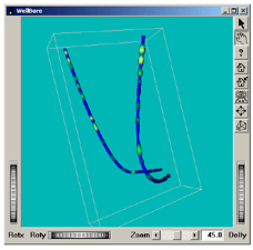
An example program showing the use of SoExtrusion SoExtrusion SoExtrusion to do a well-bore plot is provided in $OIVHOME/src/Inventor/examples/Techniques/WellBore.
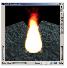
Particle system animation, managed by the base class SoParticleAnimation SoParticleAnimation SoParticleAnimation , is used for generating real-time special effects such as fire, chemical flame, explosions, fluid motion, smoke, snow, etc…
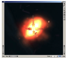
All sub-classes that are derived from SoParticleAnimation SoParticleAnimation SoParticleAnimation (e.g., SoParticleChemicalFlame SoParticleChemicalFlame SoParticleChemicalFlame , SoParticleExplosion SoParticleExplosion SoParticleExplosion ,…) have different sets of default values for their fields to produce their particular particle effect.
A particle system is a set of particles (the field numParticles specifies the size of this set) where each particle is defined by the following properties (fields of SoParticleAnimation SoParticleAnimation SoParticleAnimation ):
Shape of the particle, which is generally a rectangular billboard, i.e., a screen-aligned rectangle, which can be textured. Fields: particleShape and particleTexture.
Initial position of the particle. A particle can be emitted from a point or from a predefined shape (cylinder, sphere, disk,…) and transformed by the current cumulative transformation. If particles are emitted from a shape, they are uniformly distributed on the entire surface of this shape. Fields: emitShapeType and shapeScale.
Initial appearance (color, opacity, size), which defines the appearance of the particle at its birth. Fields: initialColor, initialOpacity, and initialSize.
Final appearance (color, opacity, size), which defines the appearance of the particle just before its death. Fields: endColor, endOpacity, and endSize.
Life span expressed in milliseconds. Field: lifeSpan.
Speed expressed in units (in modeling coordinates) per second. Fields: speed.
Direction of the particle during its life span. The direction of a particle is randomly computed at its birth to be within an elliptical cone of emission defined by two dispersion angles. In the case where particles are emitted from a solid shape (cylinder or sphere), the dispersion angles are ignored and the normal of the shape is used as the direction. Fields: dispersionAngles and emitShapeType.
All of these properties (color, opacity, size, speed, and life span) can fluctuate randomly for each particle within a specified range of values. For instance, the initial color of a particle is computed as follows:
Initial color = initialColor + (initialColor * initialColorVariation * RF)
where RF is a random value between –1 and 1.
Fields: initialColorVariation, initialOpacityVariation, initialSizeVariation, endColorVariation, endOpacityVariation, endSizeVariation, lifeSpanVariation, and speedVariation,
The appearance of a particle during its life is determined by a linear interpolation between the initial and final appearance parameters according to the time elapsed since its creation.
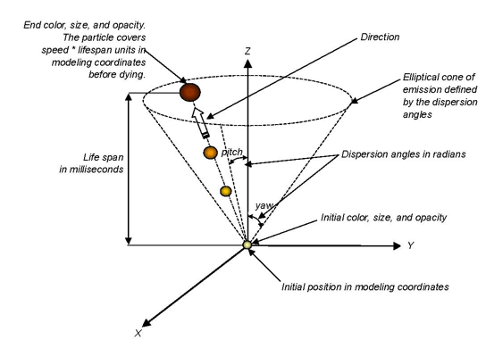
Figure 5.30, “ Life cycle of a particle” shows the life cycle of a particle emitted from a point. The particle texture (particleTexture field) is a white circle on a black background texture with zero transparency in the middle increasing linearly to full transparency on the edges. This texture is mapped onto each rectangular particle billboard.
Initialize FXViz module
This initialization must be called after initializing Open Inventor.
SoFXViz::init();Create and configure the particle system animation node
Create the particle system animation node, SoParticleAnimation SoParticleAnimation SoParticleAnimation , or one of its sub-classes (e.g. SoParticleFlame SoParticleFlame SoParticleFlame , SoParticleExplosion SoParticleExplosion SoParticleExplosion …).
SoParticleAnimation *myParticleAnimation = new SoParticleAnimation;
// Particles are emitted from a point.
myParticleAnimation->emitShapeType = SoParticleAnimation::POINT;
myParticleAnimation->numParticles = 500;            // Sets the numbers of particles
                                                    // Initial color is yellow
myParticleAnimation->initialColor.setValue(1, 1, 0);
myParticleAnimation->endColor.setValue(1, 0, 0);    // End color is red
...                                                 // Other configurations
SoParticleAnimation myParticleAnimation = new SoParticleAnimation();
// Particles are emitted from a point.
myParticleAnimation.emitShapeType.Value = SoParticleAnimation.EmitShapeTypes.POINT;
myParticleAnimation.numParticles.Value = 500;          // Sets the numbers of particles

myParticleAnimation.initialColor.SetValue(1f, 1f, 0f); // Initial color is yellow
myParticleAnimation.endColor.SetValue(1f, 0f, 0f);     // End color is red
...                                                  // Other configurations
SoParticleAnimation myParticleAnimation = new SoParticleAnimation();
// Particles are emitted from a point.
myParticleAnimation.emitShapeType.setValue(SoParticleAnimation.EmitShapeTypes.POINT);
myParticleAnimation.numParticles.setValue(500);         // Sets the numbers of particles
                                                        // Initial color is yellow
myParticleAnimation.initialColor.setValue(1f, 1f, 0f);
myParticleAnimation.endColor.setValue(1f, 0f, 0f);   // End color is red
...                                                  // Other configurations
Position and orient the particle system animation node in your 3D scene
By default, the particle emission origin is at (0,0,0) and particles are emitted within an elliptical cone whose central axis is aligned with the z-axis, with its apex at the origin.
SoRotationXYZ *myParticleOrientation = new SoRotationXYZ;
myParticleOrientation->axis = SoRotationXYZ::Y;
myParticleOrientation->value = M_PI/2.0;    // Bottom of an elliptical cone of
                                                // emission in the plane YZ
SoTranslation *myParticlePosition = new SoTranslation;
myParticlePosition.translation.setValue(5,1,2); // Position the origin of emission
                                                // at (5,1,2)
SoRotationXYZ myParticleOrientation = new SoRotationXYZ();
myParticleOrientation.axis.Value = SoRotationXYZ.AxisType.Y;
myParticleOrientation.angle.Value = (float) Math.PI/2;    // Bottom of an elliptical cone
                                                          // of emission in the plane YZ
SoTranslation myParticlePosition = new SoTranslation();
myParticlePosition.translation.SetValue(5f, 1f, 2f); // Position the origin of emission
                                                     // at (5,1,2)
SoRotationXYZ myParticleOrientation = new SoRotationXYZ();
myParticleOrientation.axis.setValue(SoRotationXYZ.AxisType.Y);
myParticleOrientation.angle.setValue((float)Math.PI/2);    // Bottom of an elliptical cone
                                                           // of emission in the plane YZ
SoTranslation myParticlePosition = new SoTranslation();
myParticlePosition.translation.setValue(5f, 1f, 2f); // Position the origin of emission
                                                     // at (5,1,2)
Add the SoParticleAnimation to the scene graph
root->addChild(myParticlePosition);
root->addChild(myParticleOrientation);
root->addChild(myParticleAnimation);
root.AddChild(myParticlePosition); root.AddChild(myParticleOrientation); root.AddChild(myParticleAnimation);root.addChild(myParticlePosition); root.addChild(myParticleOrientation); root.addChild(myParticleAnimation);
The example program $OIVHOME/src/FXViz/demos/particleAnimationEditor illustrates these steps. It allows you to adjust the SoParticleAnimation SoParticleAnimation SoParticleAnimation parameters to realize exactly the special effect you want.