Caching saves the result of an operation so that it doesn't need to be repeated. Inventor provides two kinds of caching: render caching and bounding-box caching. (See Section 8.5, “Calculating a Bounding Box” for a description of the SoGetBoundingBoxAction SoGetBoundingBoxAction SoGetBoundingBoxAction .) For both the render action and the bounding-box action, you can specify that the results of the traversal be saved in a cache. The render cache, for example, contains an OpenGL display list that results from traversing the scene graph to be rendered. If the scene graph does not change, Inventor can use the contents of this cache for subsequent renderings, without traversing the scene graph at all.
AnSoSeparator SoSeparator SoSeparator node has two fields that are used for caching. Possible values for these fields are AUTO, ON, or OFF. AUTO is the default value.
) specifies whether render caching is used. AUTO turns on caching when the scene graph below the separator is not changing. ON specifies to always try to build a cache, regardless of whether it is efficient. OFF specifies not to build or use a cache. | |
boundingBoxCaching (SoSFEnum) | specifies whether bounding-box caching is used. |
The SoSeparator SoSeparator SoSeparator class has a setNumRenderCaches() method that allows you to specify how many render caches each separator node will have. The greater the number of render caches that are built, the more memory used. You might use two caches, for example, if a viewer switches between wireframe and filled draw-styles, and the draw-style is set outside the cache. This method affects only the separator nodes that are created after it is called. Setting the number of render caches to 0 before any separators are created turns off render caching. The default number of render caches is 2.
The caching process begins with the separator group, as follows:
If a valid cache exists, the separator group ignores the scene graph below it and uses the contents of the cache.
If a valid cache does not exist, the separator group checks the appropriate field to see if it should create a cache.
If caching is ON, it opens a cache, traverses the nodes under the separator group, records the results in the cache, and then calls the cache. If caching is AUTO, Inventor uses a special set of conditions to determine whether it is efficient to create a cache.
The nodes under the separator group may inherit values from nodes that appear before the separator group in the graph. For example, materials, coordinates, texture coordinates, complexity nodes, normals, and bindings tend to be used by each shape. If these values change, the cache needs to change. (Note that if a texture outside the cache changes, the cache is still valid because the shape does not send the texture calls to OpenGL. The texture is sent directly to OpenGL when the SoTexture2 SoTexture2 SoTexture2 node is traversed.)
Be aware that these changes also invalidate the cache:
Inventor is conservative in determining whether the current cache is valid (that is, caches may be invalidated and rebuilt even if inherited values have not changed).
Figure 9.24, “ Caching a Shape ” shows a scene graph with a transform node whose values are changing frequently and a cube. In this case, turn on caching at the separator above the cube so that the changing transform values do not invalidate the cache.
Figure 9.25, “ Caching a Shape along with a Changing Property Node ” shows a scene graph with a complexity node whose values are changing frequently and a cube. Here, you would include both the property node and the shape in the same cache, since the shape always uses the property node when it is rendered.
Render caches can consume a great deal of memory, but they are very useful for speeding up rendering. Using the AUTO (default) value for render caching allows Inventor to determine whether creating a render cache will save time.
Bounding-box caching is relatively inexpensive. Inventor uses bounding- box caching to speed up picking. If bounding-box caching is on and the user picks part of the graph that contains a separator group, the separator group can first check to see if the bounding box is picked. If not, it knows nothing under it is picked and does not need to traverse the subgraph.
If you are dealing with a large scene and you know that the camera will frequently view only part of that scene, you may want to turn on render culling so that Inventor doesn't take time rendering parts of the scene that lie completely outside the camera's view. An SoSeparator SoSeparator SoSeparator node has two flags used for culling: renderCulling and pickCulling. By default, render culling is AUTO. By default, pick culling is ON.
This description deals with render culling. (Pick culling works in a similar manner and is relatively inexpensive; you will probably simply leave it ON.) Here's a brief summary of how render culling works:
The camera puts the world-space view volume into the traversal state when it is traversed.
During traversal, the separator node tests its renderCulling field. If it is ON, it culls the render area, as follows:
It computes the bounding box for the separator, in object space. (This information may be cached already.)
It transforms the bounding-box information into world space and compares it to the view volume in the state.
If the bounding box is completely outside the current view volume, the separator does not traverse its children.
Since Step 2 (computing the bounding box and testing it) is fairly expensive in terms of time, render culling is off by default. You'll need to evaluate your scene graph to determine whether render culling will be efficient. For example, you could have a large scene graph with external walls, and detailed electrical and plumbing connections beneath them. Although the scene graph is complex, culling won't help because all elements would be in the camera's view at the same time. However, for scenes where objects are widely separated in space, such as a scene graph for a solar system, culling can be very useful.
![[Tip]](../images/tip.jpg) | |
Tip: To facilitate culling, organize the database spatially so that objects that are close to each other in 3D space are under the same separator and objects far away from each other are under different separators. In the case of the scene graph with external walls, you could group the plumbing and electrical connections for each wall under a separator. |
Guidelines for turning on render culling are as follows:
In general, don't put a culling separator underneath a caching separator (that is, an SoSeparator SoSeparator SoSeparator with its renderCaching field set explicitly to ON). Use a culling separator under SoSeparator SoSeparator SoSeparator nodes with render caching set to OFF or AUTO.
The reason for this guideline is that culling depends on the camera. If a separator makes a culling decision, any cache that it is part of will depend on the camera. Caches dependent on the camera will often be broken, because in most applications, the camera changes frequently.
It's also efficient to turn on culling and caching at the same separator node (or turn on culling and leave caching at AUTO).
Turn on culling only for objects that are separated in space.
Turn on culling only for objects with a fairly large number of polygons, or deciding whether to cull might take longer than just drawing the object.
The SoSFBool SoSFBool SoSFBool field boundingBoxIgnoring has been added in some nodes in order to ignore the bounding box of the specified nodes. The value indicates whether the bounding box is ignored or not. It can be useful to ignore the bounding box for annotation geometry (for example color bars and legends) that should not be considered by the viewer’s “viewAll” operation. This field can also be used to suppress computation of the bounding box for very large or frequently modified geometry. However ignoring the bounding box of actual scene geometry can cause problems, for example with automatic adjustment of clip planes in the viewer. For scene geometry we recommend using the SoBBox SoBBox SoBBox node to specify a precomputed bounding box.
An effect similar to ignoring the bounding box could previously be accomplished using an SoResetTransform SoResetTransform SoResetTransform node to reset the bounding box. Using the boundingBoxIgnoring field or SoBBox SoBBox SoBBox node is more efficient because it avoids computing the bounding box.
The following nodes and all inherited nodes contain this field:
SoGroup SoGroup SoGroup : Prevents computation of the bounding box for all nodes below this one in the scene graph (SoGetBoundingBoxAction SoGetBoundingBoxAction SoGetBoundingBoxAction will not traverse below this node).
SoShape SoShape SoShape : Prevents computation of the bounding box for this shape.
SoBaseKit SoBaseKit SoBaseKit : Prevents computation of the bounding box for this nodekit.
This node allows the application to specify a bounding box for a portion of the scene graph. The main goal of this node is to avoid computing the bounding box when we already know it. Computing the bounding box for a large geometry (e.g. 1 million+ triangles) can be time consuming, especially if the geometry is changing, for example driven by an animation.
In this example the bounding box is computed in each node up to the node SoBBox SoBBox SoBBox . It is not computed for the nodes placed after the SoBBox SoBBox SoBBox node.
The mode field has three possible values:
SoBBox::DISABLE: The node is ignored by all actions. (The bounding box is computed for all the subsequent nodes of the scene-graph.)
SoBBox::NO_BOUNDING_BOX: Subsequent nodes in this part of the scene graph are treated as if they have no bounding box. SoGetBoundingBoxAction will stop traversing this part of the scene graph. This can be used to prevent some nodes from affecting the overall bounding box, as discussed in the section called “boundingBoxIgnoring field”.
SoBBox::USER_DEFINED: Subsequent nodes in this part of the scene graph are treated as if they have the bounding box specified in the boundingBox field. SoGetBoundingBoxAction SoGetBoundingBoxAction SoGetBoundingBoxAction will stop traversing this part of the scene graph and use the specified bounding box. If rendering in VIEW_BBOX mode (see the SoXXXViewer method setDrawStyle), SoBBox will draw the specified bounding box and subsequent nodes in this part of the scene graph will not be traversed.
This node is used in two demos:
$OIVHOME/src/Inventor/examples/Features/BufferObjects/AnimatedShape
$OIVHOME/src/Inventor/examples/Features/BufferObjects/SoBufferedShape
The first demo renders an animated textured shape. There is no need to compute the bounding box for each animation step because the formula is based on an amplified sin function and the bounding box is defined by the limits of the formula. The bounding box node is added just before the shape so the bounding box action will not compute a bounding box for the shape.
The second demo renders a huge geometry using an SoBufferedShape SoBufferedShape SoBufferedShape node. Computing the bounding box of this shape takes a long time because the geometry is stored directly on the graphic card. Therefore computing the bounding box requires uploading the data to system memory before computing the bounding box. But we can precompute the bounding box for this shape and set it using an SoBBox SoBBox SoBBox node. Changing the scale of the geometry triggers a scene graph traversal for the bounding box, but we can apply the same scale to the bounding box, there is no need to compute it using the geometry.
See the section called “Buffered Shape” for more information about SoBufferedShape SoBufferedShape SoBufferedShape .
The fast editing feature allows you to modify parts of a scene without redrawing the entire scene. For example, you could use it to interactively move a small object in a large scene that takes a long time to redraw. This feature takes advantage of the fact that only a small number of triangles will have to be redrawn rather than all of them.
To use fast editing, there are two steps:
You must specify to which parts of the scene you want to apply fast editing mode.
This is done by setting the SoSeparator SoSeparator SoSeparator fastEditing field to the desired value. Possible values are DISABLE, KEEP_ZBUFFER, and CLEAR_ZBUFFER. Using KEEP_ZBUFFER means that the fast edit geometry is depth buffered against the other objects in the scene, and using CLEAR_ZBUFFER means that the fast edit geometry will be drawn on top of the other objects of the scene. If several SoSeparator SoSeparator SoSeparator s have the CLEAR_ZBUFFER flag set, they are drawn in the order in which they appear in the scene. The last separator in the scene will be topmost on the screen.
Fast editing must be enabled in your SoGLRenderAction SoGLRenderAction SoGLRenderAction .
To do this, simply make a call to the SoGLRenderAction::setFastEditSavePolicy(param)method. It allows you to specify how the fast editing computation happens when the user interacts with the scene. Possible values are DISABLE, EACH_FRAME, and WHEN_NEEDED.
If EACH_FRAME is set, the scene buffer is saved each time the scene graph is redrawn.
If WHEN_NEEDED is set, no save is made during ordinary scene rendering. When a change to the fast editing sub-scene graph occurs, the entire scene is first rendered and saved, and then the fast edit nodes are drawn. During next rendering, only the fast edit nodes are drawn. So using this flag implies you need one more full scene traversal before starting to move your fast edit sub-scene graph interactively.
We recommend using the EACH_FRAME flag when manipulating a very large main scene graph. In this case, the time used for saving buffers is insignificant compared to the time required to draw the scene. EACH_FRAME is recommended as well when the fast editing sub-scene graph is modified frequently. User interactivity is better with the fast edit graph even if the global scene frame rate may slow down.
It would be better to use WHEN_NEEDED when the fast editing sub-scene graph changes occur very rarely. In this case, you will have full performance when rendering the main scene graph because no buffers are saved.
The fast editing feature is illustrated by the example in the $OIVHOME/src/Inventor/examples/features/fastEditing directory.
Fast editing performance depends on your graphics hardware and driver. To use the fast editing feature, the ARB_bufferRegion OpenGL extension is required.
When a fast edit object is moved outside the clip planes limit, fast editing is temporarily disabled and the entire scene is redrawn.
The topmost SoSeparator SoSeparator SoSeparator of your scene graph should not enable the fast editing feature. Otherwise, performance will be very poor.
All fast editing sub-graphs are rendered even if only one fast editing sub-graph has changed.
This feature is most efficient when the parts of a scene graph to be fast edited contain few triangles.
Large Model Viewing techniques require a spatial organization of shapes. Unfortunately, application scene graphs are often not organized spatially. The abstract node class, SoRenderList SoRenderList SoRenderList , has been developed to deal with this issue. This new node creates a flat, linear representation of the shapes within a hierarchical scene graph, which can then be traversed in any order or can be reorganized into a spatial scheme. This reorganization is transparent to the application, which receives the benefits of spatial organization without needing to change its logical organization of the scene graph.
In Open Inventor, several strategies have been implemented in the nodes SoValueOrdering, SoOctreeOrdering, and SoOcclusionCulling. Advanced programmers can derive new nodes from the SoRenderList SoRenderList SoRenderList class to implement their own large model viewing techniques.
SoFieldContainer SoFieldContainer SoFieldContainer
SoGroup
SoSeparator
Figure 9.27. Rendering node classes
The SoValueOrdering node traverses the linear list of shapes generated by the SoRenderList node and determines the rendering value and cost of each shape. The rendering value is based on the object’s approximate screen size, and its cost is based on a count of the number of primitives the shape contains.
During each render traversal, the SoValueOrdering node determines how many primitives a shape deserves based on its rendering value. If the shape contains multiple levels of detail, then the SoValueOrdering node will choose the correct level of detail. However, this node also has two techniques that allow it to handle scenes that do not contain levels of detail: bounding box substitutes and drop culling.
If bounding box substitutes are enabled and the SoValueOrdering node calculates that the number of triangles that the object deserves is closer to 12 (the number of triangles in a bounding box) than to the minimum number of triangles the shape can draw, then the SoValueOrdering SoValueOrdering SoValueOrdering node will draw a bounding box instead of the shape. With drop culling enabled, a user can specify a size in pixels such that when the shape is less than this size, the shape is not rendered.
The typical scenario where this is useful is in CAD model assembly viewing, where all or most of the scene is visible, but lots of details may be so small that there is no point in drawing them until the user zooms in on them. Replacing such detail with its bounding box is adequate in many cases and does not have the disk and memory costs, along with the preprocessing time, associated with maintaining multiple levels of detail.
SoValueOrdering SoValueOrdering SoValueOrdering has the following fields:
When it is enabled, the user can specify the size in pixels (see dropScreenArea) such that when a shape is less than this size, it is not rendered. | |
Used to specify the size in pixels for drop culling. | |
If bounding box substitutes are enabled and the SoValueOrdering node calculates that the number of triangles that the object deserves is closer to 12 (the number of triangles in a bounding box) than to the minimum number of triangles the shape can draw, then the SoValueOrdering node will draw a bounding box instead of the shape. | |
If decimate substitutes are enabled, then the SoValueOrdering will apply an SoGlobalSimpifyAction to shapes that it determines need simplification. Sometimes a shape has so many triangles that neither the bounding box nor the shape is a satisfactory choice given the shape’s calculated value. In this case, the SoValueOrdering SoValueOrdering SoValueOrdering will create and use a simplified version. The simplification is done when Inventor has been idle for over a second. | |
If low value culling is enabled, then the shape will not be rendered if the SoValueOrdering SoValueOrdering SoValueOrdering node decides that its value in triangles is not even worth rendering a bounding box. This will happen if the decimation percentage value is set very low. | |
Allows the SoValueOrdering SoValueOrdering SoValueOrdering node to adjust the decimation percentage value depending on the shape’s rendering value. See Section 18.5, “Adaptive Viewing” for a discussion of the decimation percentage value. |
Example 9.1. How to use SoValueOrdering
SoValueOrdering *valueOrdering = new SoValueOrdering;
valueOrdering->ref();

// This is the default value.
valueOrdering->dropCulling = TRUE;

// When the size of a shape is less than 40 pixels, the shape is not rendered.
valueOrdering->dropScreenArea = 40;
valueOrdering->boundingBoxSubstitutes = FALSE;
valueOrdering->decimateSubstitutes = FALSE;
valueOrdering->lowValueCulling = FALSE;
valueOrdering->adjustDecimation = FALSE;

// Read the whole file into the database
SoSeparator *root = SoDB::readAll(&mySceneInput);
if (root == NULL) return;
valueOrdering->addChild(root);
SoValueOrdering valueOrdering = new SoValueOrdering();

// This is the default value.
valueOrdering.dropCulling.SetValue(true);

// When the size of a shape is less than 40 pixels, the shape is not rendered.
valueOrdering.dropScreenArea.Value = 40;
valueOrdering.boundingBoxSubstitutes.Value = false;
valueOrdering.decimateSubstitutes.Value = false;
valueOrdering.lowValueCulling.Value = false;
valueOrdering.adjustDecimation.Value = false;

// Read the whole file into the database
SoSeparator root = SoDB.ReadAll(mySceneInput);
if (root == null) return;
valueOrdering.AddChild(root);
SoValueOrdering valueOrdering = new SoValueOrdering();

// This is the default value.
valueOrdering.dropCulling.setValue(true);

// When the size of a shape is less than 40 pixels, the shape is not rendered.
valueOrdering.dropScreenArea.setValue(40);
valueOrdering.boundingBoxSubstitutes.setValue(false);
valueOrdering.decimateSubstitutes.setValue(false);
valueOrdering.lowValueCulling.setValue(false);
valueOrdering.adjustDecimation.setValue(false);

// Read the whole file into the database
SoSeparator root = SoDB.readAll(mySceneInput);
if (root == null) return;
valueOrdering.addChild(root);
The SoOctreeOrdering SoOctreeOrdering SoOctreeOrdering node is a way to optimize performance in immersive applications. It is also a way to improve view frustum culling for the ScaleViz multipipe viewers as well as the “classical” Open Inventor viewers (Examiner Viewer, etc.).
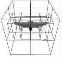
The linear list of shapes created by the SoRenderList SoRenderList SoRenderList node is processed and organized into an octree. The octree is constructed by a recursive spatial decomposition of the scene (see Figure 9.28, “ SoOctreeOrdering applied to a bird model”).
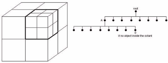
The root of the tree data structure represents the bounding box of the entire scene. This bounding box is split into eight equal octants which represent the eight children of the root. If an octant is empty, the node referencing this octant has no children. If an octant contains any objects (see Figure 9.29, “ The SoOctreeOrdering data structure”), the node referencing this octant has eight children referencing the eight new octants.
The subdivision process stops according to a per-object stop criterion based on the greatest bounding box value of this object. The smaller an object is, the deeper it is in the octree.
Using an octree data structure is very efficient for view culling because if an octant is culled, all of the objects in this octant are automatically culled. This makes it very helpful for use in walk-throughs or in other situations where the viewer is inside a large scene and much of the geometry is not visible from any given camera position. Moreover, the SoOctreeOrdering SoOctreeOrdering SoOctreeOrdering node can also use bounding box substitutes for groups of shapes that are too small to display based on an approximate screen size.
Using the octree in a multipipe rendering environment can provide significant performance improvements in some cases.
Open Inventor is multithreaded. In ScaleViz multipipe rendering, there is one render thread per pipe (see Chapter 3, ScaleViz). Each thread has a view volume associated with its pipe. The consequence is that SoOctreeOrdering SoOctreeOrdering SoOctreeOrdering node traversal allows a natural division of work between threads. The parts of the scene that are outside a view volume will be quickly culled by the octree. In other words, each render thread will basically only need to handle the part of the scene that is in the associated view volume. Keep in mind that without using the SoOctreeOrdering SoOctreeOrdering SoOctreeOrdering node, each thread would have to render the whole scene.
In addition, the algorithm “knows” that SoSeparator SoSeparator SoSeparator traversal is quicker than SoOctreeOrdering SoOctreeOrdering SoOctreeOrdering traversal, so if the scene is totally inside one pipe’s view frustum, SoSeparator SoSeparator SoSeparator traversal will be used instead of octree traversal. This is a big optimization. Indeed, the two final steps of the rendering process consist of:
Transforming vertices in the graphics pipeline (T).
Filling polygons (F).
The difference between not using the octree or using it is illustrated below (see Figure 9.30, “ Final rendering process steps – not using the octree (top) or using it (bottom)”). Assuming that the scene is entirely in pipe 1, and that the application is running on a 2-pipe machine, the final step of rendering for each thread will be:
|
Pipe1 |
Pipe2 |
|
|---|---|---|
|
Thread1 |
T,F |
0 |
|
Thread2 |
0 |
T |
|
Pipe1 |
Pipe2 |
|
|---|---|---|
|
Thread1 |
T,F |
0 |
|
Thread2 |
0 |
0 |
Figure 9.30. Final rendering process steps – not using the octree (top) or using it (bottom)
It is very important to keep in mind that SoOctreeOrdering SoOctreeOrdering SoOctreeOrdering traversal takes more time than “classic” (SoGroup SoGroup SoGroup , SoSeparator SoSeparator SoSeparator …) traversal. This is why, to see a performance increase, the scenario must be one where the SoOctreeOrdering SoOctreeOrdering SoOctreeOrdering node will do less work than an SoSeparator SoSeparator SoSeparator or SoGroup SoGroup SoGroup node. Which is typically the case when:
Your application is running in ScaleViz multipipe mode (MP viewer) and your scene is frequently contained entirely in one of the pipes as explained above.
You are walking through a scene that is composed of several objects. (If you’re walking through a scene composed of just one object, in every case the application will have to render the entire scene.) So, if your scene is a town composed of several buildings and you are inside one of the buildings, then, because of the octree, Open Inventor will only render what is around you in the building and cull the rest of the town.
![[Important]](../images/important.jpg)
After reading this paragraph, some of you will think: “This feature is not for me, I only visualize scenes composed of a single large object.” Well, Open Inventor provides a solution. If your scene is composed of only one object that is either an SoIndexedFaceSet SoIndexedFaceSet SoIndexedFaceSet or an SoIndexedTriangleStripSet SoIndexedTriangleStripSet SoIndexedTriangleStripSet node, then by using the new SoSplitGeometryAction SoSplitGeometryAction SoSplitGeometryAction (see the section called “ Split Geometry Action” for more information) action, you can split your scene into as many parts as your geometry allows. This action enables you to take advantage of the SoOctreeOrdering SoOctreeOrdering SoOctreeOrdering node.
As explained above, if you run your application in multithreaded mode, work can be divided between the threads, thus improving wireframe rendering performance. However, there are also some limitations.
For example, on a single processor machine, running a multithread application means there are several threads. However, since there is still only one processor, each thread is handled by this single processor, one at a time. Every thread is allocated a very small amount of time to run on the CPU. There is no real parallel execution. Because dividing work between two threads on a single processor machine is essentially the same (as far as time is concerned) as giving all the work to one thread, you may not see improved performance on a single processor machine.
SoOctreeOrdering SoOctreeOrdering SoOctreeOrdering has the following fields:
dropCulling (SoSFBool) | Enables/disables culling of shapes that would be smaller on the screen than the dropScreenArea threshold. |
dropScreenArea (SoSFUint32) | Sets threshold in pixels for drop culling and bounding box substitutes. |
boundingBoxSubstitutes (SoSFBool) | Enables/disables use of bounding boxes for octree cells (containing shapes) that would be smaller on the screen than the dropScreenArea threshold. |
useMovingQueue (SoSFBool) | Sets how this node should handle moving render objects. If TRUE, then moving objects are kept in a separate render list, and are not sorted into the octree, meaning that they will not be drop culled. If FALSE, moving objects will be sorted into the octree after each motion, taking more time, but enabling drop and view frustum culling for the moving objects. |
adjustDecimation (SoSFBool) | If TRUE, the octree will alter the decimation percentage for objects depending on how large they are in the view. This causes objects closer to the camera to be displayed with more detail than objects further away. |
SoOctreeOrdering SoOctreeOrdering SoOctreeOrdering has the following methods:
void setOctreeDrawing(SbBool enable) | Allows you to visualize the octree and see how it organizes your scene. |
SbBool isOctreeDrawing () | Returns TRUE if drawing is on, else returns FALSE. |
void SoOctreeOrdering::setReportCB(SoReportCB *func, void *userData) | You can set a callback for your octree to find out how many objects were rendered by each thread and other details. Your callback must have the following type: void myCallback (SoOctreeOrdering *node, int numObjTotal, int numObjRendered, void *userData) |
| |
If you set the environment variable OIV_DRAW_OCTREEto 1, the octree will draw itself each time you use it. |
Example 9.2. How to use the SoOctreeOrdering node
SoOctreeOrdering *octreeOrdering = new SoOctreeOrdering();
octreeOrdering->ref();

// This is the default value.
octreeOrdering->dropCulling = TRUE;

// When the size of a shape is less than 40 pixels,
// the shape is not rendered.
octreeOrdering->dropScreenArea = 40;

// Read the whole file into the database
SoSeparator *root = SoDB::readAll(&mySceneInput);
if (root == NULL)
{
  fprintf(stderr, "Problem reading file\n");
  return;
}

octreeOrdering->addChild(root);
SoOctreeOrdering octreeOrdering = new SoOctreeOrdering();

// This is the default value.
octreeOrdering.dropCulling.Value = true;

// When the size of a shape is less than 40 pixels,
// the shape is not rendered.
octreeOrdering.dropScreenArea.Value = 40;

// Read the whole file into the database
SoSeparator root = SoDB.ReadAll(mySceneInput);
if (root == null)
{
  Console.WriteLine("Problem reading file");
  return;
}

octreeOrdering.AddChild(root);
SoOctreeOrdering octreeOrdering = new SoOctreeOrdering();

// This is the default value.
octreeOrdering.dropCulling.setValue(true);

// When the size of a shape is less than 40 pixels,
// the shape is not rendered.
octreeOrdering.dropScreenArea.setValue(40);

// Read the whole file into the database
SoSeparator root = SoDB.readAll(mySceneInput);
if (root == null)
{
  System.err.println("Problem reading file");
  return;
}

octreeOrdering.addChild(root);
Open Inventor provides several culling operations, e.g., back face culling and view frustum culling, that remove faces or objects that do not need to be rendered. However, none of these prevent occluded objects (an object entirely behind another one, which means that the object will not contribute to the final image) from being drawn. An occluded object needlessly increases depth complexity. The SoOcclusionCulling SoOcclusionCulling SoOcclusionCulling node culls those objects.
The occlusion test is performed with an OpenGL-based occlusion test. The node uses its render list, sorts the objects from front to back, draws the first one, and then asks the board if the second closest object is occluded by the first. The object is occluded if none of its bounding box’s pixels would have been written in the Z-buffer, which means the first object entirely hides the second one (every second object’s pixels are located in the same array than first object’s pixels which all have a greater z value). If it is not occluded, then the object is drawn and becomes an occluder for the next object (more pixels are in the Z-buffer) and so on.
![[Warning]](../images/warning.jpg) | |
Occlusion culling requires the HP_OCCLUSION_TEST. If this extension is not available, SoOcclusionCulling SoOcclusionCulling SoOcclusionCulling behaves the same as an SoSeparator SoSeparator SoSeparator . |
The occlusion node is useful in walk-through type applications. For example, if the scene is a town and the camera is inside a building, only that building would be drawn, and all others would be occluded.
It also can help in CAD applications. For example, if the camera looks at the exterior of a detailed model of a car (including all the pieces that compose it), essentially only the car’s body would be drawn as the rest of it (engine, transmission, etc.) would be occluded.
Sometimes doing an occlusion test for every object of the scene at each frame is time consuming. Moreover, an occluder at frame n is often still an occluder at frame n+1. That’s why the occlusion node provides an approximate occlusion mode where at frame 1, a set of occluders is determined. From frame 2 to N-1 (where N is set with the setNumFrame method, default is 6), the set of occluders is always drawn in the Z-buffer and only previous occluded object are retested against them. At frame N, a global occlusion test is performed on all objects. To activate the mode use setApproximateOcclusion(TRUE).
On boards that support it, the NV_OCCLUSION_QUERY extension will be used to do the occlusion test (against the set of occluders). To turn off the use of the extension and switch back to HP_OCCLUSION_TEST, use the setUseHPExtension method.
The advantage of using the “NV” extension is that it allows you to know how many pixels have been written in the Z-buffer. You can set a threshold (number of pixels, default is 10). Objects that write fewer pixels than the threshold to the Z-buffer will be culled. To change the threshold, use the setThreshold() method.
The occlusion node is typically used at the top of a scene graph:
SoOcclusionCulling *occlusion = new SoOcclusionCulling;
occlusion->ref();

SoSeparator *myScene = SoDB::readAll(&mySceneInput);

occlusion->addChild(myScene);
SoOcclusionCulling occlusion = new SoOcclusionCulling();

SoSeparator myScene = SoDB.ReadAll(mySceneInput);

occlusion.AddChild(myScene);
SoOcclusionCulling occlusion = new SoOcclusionCulling();

SoSeparator myScene = SoDB.readAll(mySceneInput);

occlusion.addChild(myScene);
You can chain the SoOcclusionCulling SoOcclusionCulling SoOcclusionCulling node with an SoOctreeOrdering SoOctreeOrdering SoOctreeOrdering node. The SoOctreeOrdering SoOctreeOrdering SoOctreeOrdering node will process its SoRenderList SoRenderList SoRenderList , and pass on only visible objects (inside the viewing frustum) to the occlusion node. This last one thus has less work to do. Be sure to set the isHead field of the occlusion node to FALSE to prevent the node from creating an unnecessary SoRenderList SoRenderList SoRenderList (it should use the one from the octree node).
To use both nodes, simply create a scene graph with a top SoOctreeOrdering SoOctreeOrdering SoOctreeOrdering node having an SoOcclusionCulling SoOcclusionCulling SoOcclusionCulling node as its child, and the occlusion node having your scene as its child:
SoOctreeOrdering *octree = new SoOctreeOrdering;
octree->ref();

SoOcclusionCulling *occlusion = new SoOcclusionCulling;
occlusion->ref();
occlusion->isHead.setValue(FALSE);

SoSeparator *myScene = SoDB::readAll(&mySceneInput);

octree->addChild(occlusion);
occlusion->addChild(myScene);
SoOctreeOrdering octree = new SoOctreeOrdering();

SoOcclusionCulling occlusion = new SoOcclusionCulling();
occlusion.isHead.Value = false;

SoSeparator myScene = SoDB.ReadAll(mySceneInput);

octree.AddChild(occlusion);
occlusion.AddChild(myScene);
SoOctreeOrdering octree = new SoOctreeOrdering();

SoOcclusionCulling occlusion = new SoOcclusionCulling();
occlusion.isHead.setValue(false);

SoSeparator myScene = SoDB.readAll(mySceneInput);

octree.addChild(occlusion);
occlusion.addChild(myScene);