After reading this section, you’ll know how to use the CSG module to make Constructive Solid Geometry (CSG ).
The CSG extension provides solid modeling nodes for describing 3D shapes as combinations of other shapes using Boolean operations such as merge, intersection, and subtraction.
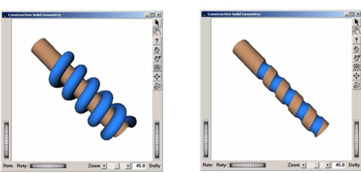
CSG stands for Constructive Solid Geometry. It is a powerful method for describing a 3D shape as a combination of simpler 3D shapes using the Boolean operations merge (union), intersection, and subtraction. For instance, the expression "(A-B)+C" means remove B from A, then merge the result with C. This is called a CSG expression, describing a CSG tree.
Actual computation of the geometry resulting from a CSG expression can be a slow process, at least not fast enough for real-time updates in interactive applications. However a visual simulation of a CSG shape can be achieved in many cases at interactive speed by using a special rendering method taking advantage of accelerated OpenGL rendering and the stencil buffer.
SolidViz implements a visual simulation of CSG shapes. A new group node, SoCSGGroup SoCSGGroup SoCSGGroup , allows the specification of a CSG expression.
![[Note]](../images/note.jpg)
SoSolidViz SoSolidViz SoSolidViz
Initialization class used to initialize and get information about the CSG module.
SoCSGGroup SoCSGGroup SoCSGGroup
Group node for interactive CSG rendering which performs a Constructive Solid Geometry (CSG) renderingThis group node performs a Constructive Solid Geometry (CSG) rendering. The children of this group define the solids that are involved in the CSG rendering. It is important to know that all children of this group are assumed to be solid (i.e., having a closed surface). Otherwise the results may be incorrect.
An expression is a character string which specifies the operations between solids. The operations can be intersection(indicated as “.” in the expression), union (“+”), or subtraction(“-”).
A solid is identified by a letter in the expression and corresponds to the child number of the SoCSGGroup SoCSGGroup SoCSGGroup as follows: “A” corresponds to child 0, “B” corresponds to child 1, and so forth. The expression is not case sensitive.
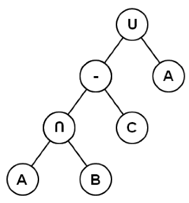
Thus a CSG expression could be: “A . B - C + A” which means compute the intersection of A and B, then remove C, then merge with A and corresponds to the CSG tree in Figure 9.22, “ An example CSG tree”.
A letter in the CSG expression can be followed by a number to indicate the convexity of the solid. The convexity of a solid is defined as the maximum numbers of pairs of front and back surfaces. For instance, the convexity of a cube is 1 whereas the convexity of a torus is 2. The convexity of a solid is assumed to be 1 if no digit follows the corresponding letter in the expression. The maximum allowable convexity value is 128.
The CSG tree defined by expressionis assumed to be in normal form (normalized). A CSG tree is in normal form when all intersection and subtraction operators have a left subtree that contains no union operator and a right subtree that is simply a shape. For example, the tree shown in Figure 9.22, “ An example CSG tree”, is in normal form.
A CSG tree can be converted to normal form by repeatedly applying the following set of production rules to the tree and then its subtrees:
Step 1: Initialize SolidViz module.
This initialization must be called after initializing Open Inventor.
SoSolidViz::init();
Step 2: Create an SoCSGGroup object.
Create the group node which will contain the shapes of the CSG model.
SoCSGGroup *myCSGGroup = new SoCSGGroup;
SoCSGGroup myCSGGroup = new SoCSGGroup();
SoCSGGroup myCSGGroup = new SoCSGGroup();
Step 3: Add the solid shapes to the SoCSGGroup.
Add as many children to the SoCSGGroup SoCSGGroup SoCSGGroup as there are solid shapes.
SoCube *myShapeA = new SoCube;
SoSphere *myShapeB = new SoSphere;
myCSGGroup->addChild(myShapeA);     // The first child is interpreted as the solid A
myCSGGroup->addChild(myShapeB);     // The second child is interpreted as the solid B
SoCube myShapeA = new SoCube();
SoSphere myShapeB = new SoSphere();
myCSGGroup.AddChild(myShapeA);     // The first child is interpreted as the solid A
myCSGGroup.AddChild(myShapeB);     // The second child is interpreted as the solid B
SoCube myShapeA = new SoCube();
SoSphere myShapeB = new SoSphere();
myCSGGroup.addChild(myShapeA);     // The first child is interpreted as the solid A
myCSGGroup.addChild(myShapeB);     // The second child is interpreted as the solid B
![[Tip]](../images/tip.jpg) | |
Each child of the SoCSGGroup SoCSGGroup SoCSGGroup must correspond to a solid shape. If your solid shape is composed of several nodes (e.g., transformation nodes, property nodes, shape nodes,…), add all these nodes as children of an SoSeparator SoSeparator SoSeparator , then add this separator as a child of SoCSGGroup SoCSGGroup SoCSGGroup . |
![[Warning]](../images/warning.jpg) | |
Each shape added under an SoCSGGroup SoCSGGroup SoCSGGroup must be solid (i.e., a closed shape) to obtain correct results. |
Step 4: Specify the expression of the SoCSGGroup.
The CSG expression relating the solid shapes of SoCSGGroup SoCSGGroup SoCSGGroup must be specified though the expression field. The expression for subtracting shape B from shape A is: “A-B”.
myCSGGroup->expression.setValue("A-B");  // The sphere (solid B)
                                         // is subtracted from the cube (solid A)
myCSGGroup.expression.SetValue("A-B");  // The sphere (solid B)
                                        // is subtracted from the cube (solid A)
myCSGGroup.expression.setValue("A-B");  // The sphere (solid B)
                                        // is subtracted from the cube (solid A)
| |
The expression must be normalized. |
Step 5: Add the SoCSGGroup to the scene graph.
root->addChild(myCSGGroup);
root.AddChild(myCSGGroup);
root.addChild(myCSGGroup);
The example program:
$OIVHOME/src/SolidViz/examples/csgGroup.cxx
illustrates these steps.
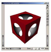
Picking on a CSG rendering may not work as expected. SoCSGGroup SoCSGGroup SoCSGGroup produces the visual effect of the specified CSG operations, but the actual geometry is not modified. Open Inventor picking operates on the actual geometry. For example, if a cube has a cylindrical “hole” cut out of it using CSG rendering, picking on the “hole” will return a pick path to the geometry used to cut out the hole.
CSG rendering (i.e., SoCSGGroup SoCSGGroup SoCSGGroup ) requires that an OpenGL stencil buffer exist for the Open Inventor drawing window. For best performance, the graphics accelerator should do stencil buffer operations in hardware.
| |
On Microsoft Windows, you can “hint” to the Pixel Format chooser that stencil buffer support is very important by setting the environment variable OIV_REQUIRE_STENCIL. |
CSG rendering requires two or (potentially many) more rendering passes, which will reduce performance. The number of passes is related to the complexity of the CSG expression and to the convexity of the geometry. Consequently, a good graphics accelerator is highly recommended.
You must also be aware that the more complex the CSG expression is, the slower the performance. The same holds true for the convexity of an object – greater convexity implies slower performance. Furthermore, if the CSG expression exceeds a certain length, a save/restore of the depth is needed and this operation is time consuming. The environment variable OIV_CSG_BUFFER_REGION on Windows allows you to speed up this task (see the SoCSGGroup SoCSGGroup SoCSGGroup reference manual text for more information).