-
Interface Summary Interface Description SbImageDataAccessor.Region A region must be an ordered set with a first voxel and for each voxel a next voxel, else we cannot associate a buffer to this region. -
Class Summary Class Description SbChannelList List of channel to extract.SbDiscreteLineProfile Profile line extractor Define a profile line extractor based on the Bresenham's Line algorithm.SbImageDataAccessor Class used to retrieve data from anSoImageDataAdapter.SbImageDataAccessor.SubVolumeRegion Regionrepresenting a 3D box.SbImageDataAdapterHelper Helper class forSoImageDataAdapter.SbImageDataType Basic class representing multi channel DataType.SbKernel2i32 Integer 2D-Kernel for morphological operations.SbKernel3i32 Integer 3D-Kernel for morphological operations.SoImageViz Module class use to register/unregister ImageViz module.
Package com.openinventor.imageviz Description
- License:
ImageViz is a separately licensed Open Inventor extension. You need an ImageViz license string in addition to your Open Inventor license string. - Windows:
Open Inventor ImageViz module extension supports Windows 64-bits and 32-bits for Visual Studio C++ 2010/2012/2013 and 2015. - Other OS:
Open Inventor ImageViz module extension supports also Linux 64-bits RHEL 5, RHEL6 and Mac OS X. - Exceptions:
Unlike Open Inventor core (and most other extensions), ImageViz handles some detected errors by throwing an exception (see SbException). These cases are noted in the documentation.
| Important notices:
|
Specifically designed for application developers, the Open Inventor
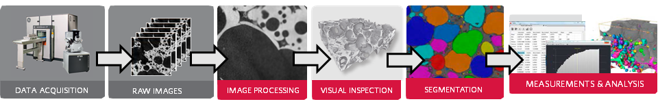
Open Inventor ImageViz SDK provides an extensive collection of high-performance parallelized 2D/3D image processing and analysis operators to implement application workflows, including:
- Pre-processing: 2D/3D image cleaning and enhancement
- Segmentation: identification of objects, phases, defects, and regions of interest
- Analysis: data quantification and numerical results Process a wide range of image data, including 2D and 3D, grayscale and color, various bit-depth images, data from X-ray tomography, electron and optical microscopy, MRI, or other image acquisition systems. Implement automated image processing and analysis workflows and provide software users with faster, more accurate, and more complete insight into their data.
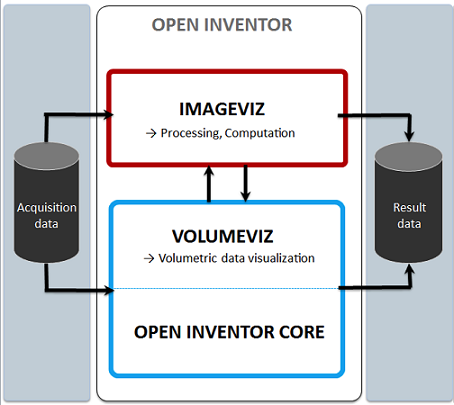
ImageViz is tightly integrated into the Open Inventor SDK and its standard concept of engines, nodes, and fields. Open Inventor data objects can be connected as input to ImageViz processing engines. Moreover, any ImageViz engine
This section introduces how to start working with ImageViz from scratch. Each demo below provides an example for performing a step of a classical image processing chain.
Please note when using the ImageViz documentation: At the top of each engine's page there is a link to a page containing general information about the algorithms used in that group of engines.
The pre-processing step helps to enhance the quality of the image thanks to an image processing filter.
- For more information about image filtering, see section Image Filtering.
- For more information about smoothing and denoising images, see section Smoothing And Denoising.
1.1 Denoising a 2D image This example shows how to denoise an image using a median filter.
First it is shown how to load a 2D image from a file into an SoImageDataAdapter object.
- Then a denoising filter is applied with the
SoMedianFilterProcessingengine. - At least a simple scene graph is built and the image is displayed in a viewer through an
SoImageobject.
This example shows how to denoise an image using a bilateral filter.
First it is shown how to load a 3D image from a file into an SoImageDataAdapter object.
- Then a denoising filter is applied with the
SoBilateralFilterProcessingengine. - At least a simple scene graph is built and the image is displayed in a viewer with a volume rendering.
Segmentation is a very important step of an image processing workflow. This is where objects to identify in the scene are isolated in a binary or label image.
- For more information about image segmentation, see section Image Segmentation.
2.1 Segmentation by thresholding This example shows how to create a binary image from an input grayscale image with a classic thresholding operator. The input image is shown with the resulting thresholded image as overlay.
The input grayscale image is loaded in an
SoImageDataAdapterobject.- A binary image is generated as output of the
SoThresholdingProcessingengine. - A scene graph is built to display the original image in a viewer with the binary image as overlay.
2.2 Segmentation by flood fill This example shows how to create a binary image from an input grayscale image performing a region growing from a seed point. The center of the image, that belongs to the dark shape to detect, is taken as the seed point. The input image is shown with the boundaries of the resulting thresholded image as overlay.
The input grayscale image is loaded in an
SoImageDataAdapterobject.- A binary image is generated as output of the
SoFloodFillThresholdProcessingengine. - The boundaries of the binary image are extracted with the
SoObjectBoundariesProcessingengine for a display without hiding inside the object. - A scene graph is built to display the raw image in a viewer with the binary boundary image as overlay.
3 Image Quantification Image analysis is the final step of an image processing workflow when its aim is to quantify the contents of a scene. This is where we take out the numerical results from the segmented image.
- A binary image is generated as output of the
- For more information about image analysis, see section Image Analysis .
3.1 Label analysis This example shows how to compute two native measurements on a segmented binary image.
Once the input image is loaded, the SoLabelingProcessing engine is applied to assign a different label to each object of the scene.
- Then the
SoLabelAnalysisQuantificationengine is used with two measurements: the equivalent diameter and the Feret diameters ratio (shape factor of elongation). - The results measured on the image objects are printed in the console. The code shows how to access to the result data.
ImageViz proposes a substancial set of native measures . However it may be necessary to define its own formula to be computed in a label analysis.
This example shows how to define a custom measure.
The workflow is almost the same as the Label analysis example.
- A custom circularity factor is created with an
SoDataMeasureCustomobject. - This custom measure is set in an
SoLabelAnalysisQuantificationengine and computed for each particle.
Some of the ImageViz native measures have attributes (measures related to Ferets diameters, histogram computation or cooccurrence matrix).
This example shows how to modify the attributes of a measure.
The Feret's diameter ratio computes the ratio between 2 Feret's diameter. Depending on the angular step used to compute the distribution of Feret's diameters, the precision of the result can change.
The workflow is almost the same as the Label analysis example.
- Two different
SoLabelAnalysisQuantificationengines are intialized. - The first one keeps the default distribution of Feret diameters (10 diameters, each 18 degrees).
- The second one takes a new distribution of Feret diameters (90 diameters, each 2 degrees).
- Both analysis are computed and both results of the most elongated particle are displayed to show the impact of this change.
This section contains examples for handling input and output data.
This example demonstrates how to create a new 2D image containing data from a buffer.
First it is shown how to fill an SoCpuBufferObject with synthetic values that would represent a bright square on a gray background.
Then this buffer is set in an SoMemoryDataAdapter that corresponds to a 2D 512x512 image.
At least a simple scene graph is built and the image is displayed as an orthoslice in a viewer.
This example demonstrates how to create a new 3D image containing data from a buffer.
First it is shown how to fill an SoCpuBufferObject with synthetic values that would represent a bright 3D bar on a gray background.
Then this buffer is set in an SoMemoryDataAdapter that corresponds to a 3D 256x256x32 image.
At least a simple scene graph is built and the image is displayed in a viewer with as a volume rendering.
It is sometimes necessary to select a Region Of Interest (ROI) inside an image. This allows removing non relevant data or saving computation time during the validation step of a workflow.
This example shows how to load an image from a file into an SoImageDataAdapter object.
- Then a rectangular region [30, 100]x[30, 100]x[0, 0] pixels is extracted in an
SoMemoryDataAdapter. - The ROI is saved to file "output.tif" in the current directory.
Once an image processing chain has been validated on a set of representative samples it can be useful to apply the same workflow on a stack of images located in a same folder.
This example shows how to apply a gradient operator on a list of images and save the result in a new file.
A list of every TIFF files located in a given directory is defined (/ImageViz/Data).
- Each image is loaded.
- A Sobel gradient operator is applied on each input image.
- The output data is converted to 8 bits type (the gradient output of an 8 bits image is a 16 bits image).
- The result image is saved in another directory (the current directory).
These examples illustrates how a standard image processing workflow can be implemented. Each step is applied from loading a grayscale image to displaying results of an analysis.
All parameters of the workflow engines are exposed in the user interface, the user can change the parameters and verify the result on the output image.
- Extract measurements from a grayscale image.
- Digital rock pore analysis.