When using a display configuration with projection systems, it is often the case that the projected images are overlapped and blended to minimize visibility of the “seam” between the projected images. In order to handle this effect, it is possible to tell each ScaleViz window to render a slightly bigger portion of the scene, so when the two pictures are superposed, the overall picture is visually correct.
ScaleViz has the ability to modify the viewport regions of the rendering windows. The SoFlatScreen SoFlatScreen SoFlatScreen node has a set of four SoSFFloat SoSFFloat SoSFFloat fields, rightOverlap, leftOverlap, topOverlap, bottomOverlap, that can be used to stretch (or shrink) the viewport in all directions.
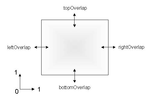
The values of the fields can be negative or positive. A negative value moves the edge of the viewport towards the left (for left/rightOverlap) or towards the bottom (for top/bottomOverlap). A positive value moves the edge of the screen view volume towards the right (for left/rightOverlap) or towards the top (for top/bottomOverlap). Usually it won’t be necessary to set all four edge blending overlap values (by default, they are set to 0).
![[Note]](../../images/note.jpg) | |
The overlap values are in the range [0.0, 1.0]. The viewport values of the ScaleViz window are modified with the overlap values. The edge blending values can be converted to pixels. If your virtual display has a width of 1280 pixels, then an overlap factor of 0.01 represents an overlap of 12 pixels. |
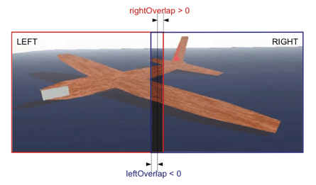
In a RIGHT-LEFT configuration, the configuration file is:
FlatScreen
  {
    name "LEFT"
    display "0.1"
    view LEFT
    rightOverlap 0.01
  }
FlatScreen
  {
    name "RIGHT"
    display "0.0"
    view RIGHT
    leftOverlap -0.01
  }
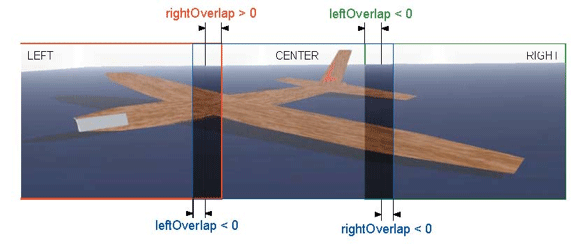
Internally, ScaleViz will set the viewport of the “ LEFT ” window to [0, 0, 0.5, 1] and then modify it per the rightOverlap value to [0, 0, 0.51, 1]. The viewport of the “ RIGHT ” window is set to [0.5, 0.0, 1.0, 1.0] and modified by the leftOverlap value. The resulting viewport is [0.49 0.0 1.0 1.0]. For a three-pipe configuration using edge overlapping, the configuration file should be:
SoFlatScreen
  {
    name "LEFT"
    display "0.1"
    view LEFT
    rightOverlap 0.01
  }
SoFlatScreen
  {
    name "CENTER"
    display "0.0"
    view CENTER
    leftOverlap -0.01
    rightOverlap 0.01
  }
SoFlatScreen
  {
    name "RIGHT"
    display "0.0"
    view RIGHT
    leftOverlap -0.01
  }
ScaleViz can do “ per-pipe stereo.” This is a special feature that applies to two-pipe systems. Instead of rendering a portion of the scene in each rendering window, the entire scene is rendered by each window, but with a slightly different point of view. The first window renders the left eye view and the second window renders the right eye view. In order to use this feature, the SoFlatScreen SoFlatScreen SoFlatScreen nodes must have their view keyword set to STEREO_LEFT and STEREO_RIGHT respectively.
It is possible to do passive stereo using this feature and the appropriate projection system. Two projectors with polarized lenses are needed to superpose the two pictures, and polarized glasses are needed to separate the left and right pictures.
The following file describes a two-pipe configuration (displays :0.0 and :0.1). Multithreading is disabled (threads SEQUENTIAL). The windows are displayed in full screen mode (default).
#Inventor V2.1 ascii

Separator
  {
  SoMPConfig
    {
    threads SEQUENTIAL
    }
  SoFlatScreen
    {
      display :0.0
      name "LEFT"
      view STEREO_LEFT
    }
  SoFlatScreen
    {
      display :0.1
      name "RIGHT"
      view STEREO_RIGHT
    }
  }